Defender (1999-2002). Manual — part 33
ENGINE
23
REPAIR
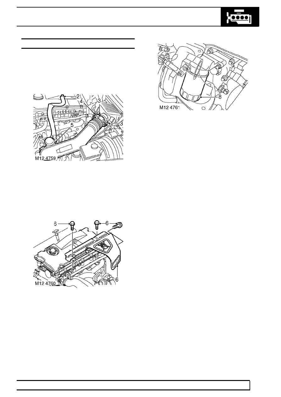
FILTER - OIL
Service repair no - 12.60.04
Remove
1. Remove 3 bolts and remove engine acoustic
cover.
2. Release clip and disconnect breather hose from
camshaft cover.
3. Release clips and disconnect air flow meter from
air filter.
4. Disconnect multiplug from air flow meter.
5. Loosen clip screw and remove air inlet hose
from turbocharger.
6. Remove 3 bolts and remove manifold heat
shield.
7. Clean area around filter head and place a
container beneath engine.
8. Using a strap wrench, unscrew and discard filter.
Refit
9. Clean mating face of filter head.
10. Lubricate sealing ring of new filter with clean
engine oil.
11. Fit filter and tighten by hand until it seats then
tighten a further half turn.
12. Start and run engine to check for leaks.
13. Stop engine, wait a few minutes, then check oil
level.
14. Top up engine oil.
15. Position exhaust manifold heat shield and
tighten 3 bolts.
16. Position air inlet hose to turbocharger and
tighten clip screw.
17. Connect air flow meter to air filter and secure
clips.
18. Connect air flow meter multiplug.
19. Connect breather hose and secure with clip.
20. Position engine acoustic cover.

12
ENGINE
24
REPAIR
STRAINER - OIL PICK-UP
Service repair no - 12.60.20
Remove
1. Remove sump gasket. See this Section.
2. Remove 3 Torx screws securing oil pick-up
strainer.
3. Remove and discard ’O’ring.
Refit
4. Clean oil pick-up strainer faces.
5. Fit new ’O’ ring to oil pick-up strainer.
6. Fit oil pick-up strainer, apply Loctite 242 to
threads of Torx screws; fit screws and tighten to
10 Nm (7 lbf.ft).
7. Fit new sump gasket. See this Section.
PUMP - OIL
Service repair no - 12.60.26
Remove
1. Remove sump gasket. See this Section.
2. Remove bolt securing oil pump sprocket to oil
pump drive spindle.
3. Remove sprocket from oil pump.
4. Remove 3 Torx screws securing oil pick-up
strainer; remove strainer.
5. Remove and discard ’O’ ring.

ENGINE
25
REPAIR
6. Using sequence shown, remove and discard 22
bolts securing oil pump and stiffener assembly.
7. Remove oil pump and stiffener assembly.
NOTE: Dowel located.
8. Remove and discard ’O’ ring.
Refit
9. Clean mating faces of oil pump and stiffener
assembly to main bearing caps and cylinder
block.
10. Fit new ’O’ ring to oil pump housing.
11. Position oil pump and stiffener assembly on to
cylinder block ensuring 2 dowels are correctly
located.
12. Fit new bolts and using sequence shown, tighten
to 13 Nm (10 lbf.ft) .
13. Lubricate a new ’O’ ring with engine oil and fit to
oil pick-up strainer.
14. Fit oil pick-up strainer, apply Loctite 242 to
threads of Torx screws; fit screws and tighten to
10 Nm (7 lbf.ft).

12
ENGINE
26
REPAIR
15. Position oil pump drive sprocket and chain on to
oil pump ensuring that the ’D’ shape on the drive
sprocket is located on flat on the oil pump drive
shaft.
16. Clean oil pump drive sprocket retaining bolt and
apply Loctite 242 to bolt threads.
17. Fit oil pump drive sprocket retaining bolt and
tighten to 25 Nm (18 lbf.ft).
18. Fit new sump gasket. See this Section.
GASKET - ENGINE TO SUMP
Service repair no - 12.60.38
Remove
1. Remove battery cover.
2. Disconnect battery negative lead.
3. Remove exhaust front pipe. See MANIFOLD
AND EXHAUST SYSTEM, Repair.
4. Drain engine oil.
5. Loosen 4 bolts securing sump to gearbox bell
housing.
6. Remove 2 bolts securing centrifuge drain pipe to
sump and discard gasket.
7. Using sequence shown and noting their fitted
position, remove 20 bolts securing sump.
8. Remove sump, remove and discard gasket.
CAUTION: Do not lever between sump and
cylinder block.
Нет комментариевНе стесняйтесь поделиться с нами вашим ценным мнением.
Текст