Defender (1999-2002). Manual — part 29

ENGINE
7
REPAIR
14. Disconnect MAP sensor multiplug from inlet
manifold.
15. Position engine harness clear of inlet manifold.
16. Disconnect vacuum hose from EGR valve.
17. Loosen clip screw and disconnect air intake
hose from EGR valve.
18. Release 3 clips and disconnect coolant hoses
from fuel cooler.
19. Disconnect fuel hoses, tank to fuel cooler and
connector block on cylinder head.
CAUTION: Plug the connections.
20. Disconnect fuel hose from fuel cooler and secure
to connector block on cylinder head. This is to
prevent contamination of the fuel injection
system.
12
ENGINE
8
REPAIR
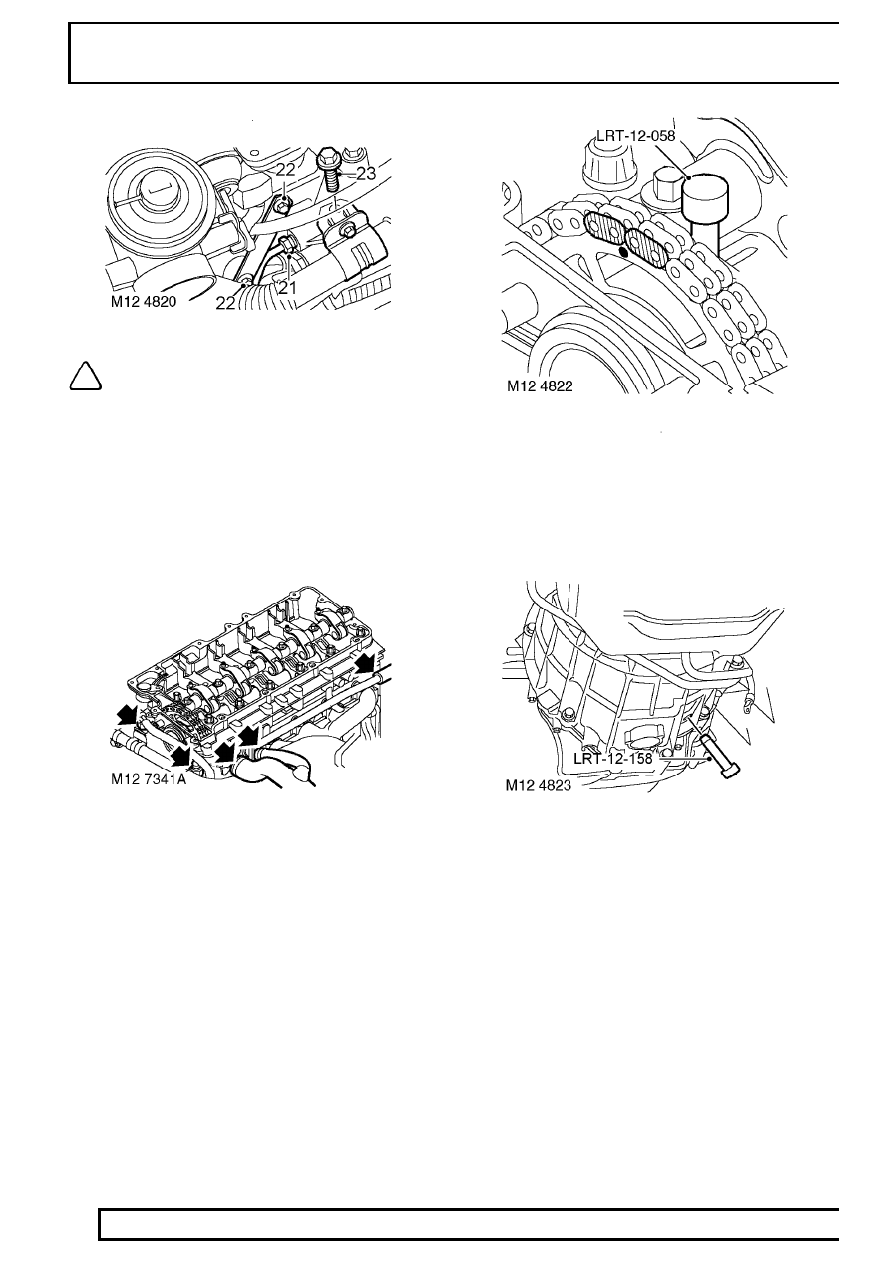
NOTE: Non EU3 model illustrated.
21. Loosen vacuum pipe union from cylinder head
and discard ’O’ ring.
22. Loosen 2 bolts and release alternator support
bracket from cylinder head.
23. Pre EU3 model:- Remove bolt securing EGR
valve pipe to cylinder head.
24. EU3 model:- Release the clips and disconnect
the coolant hoses from the EGR cooler.
25. Release clips and disconnect top hose, heater
hose and heater feed hose.
26. Remove the nut and bolt securing the cuylinder
head to the timing chain cover.
27. Rotate engine clockwise to align mark on
camshaft sprocket between coloured links on
timing chain.
28. Position LRT-12-058 through camshaft carrier to
lock camshaft.
29. Position LRT-12-158 through gearbox bell
housing to lock crankshaft.

ENGINE
9
REPAIR
30. Remove timing chain tensioner and discard
sealing washer.
31. Remove timing chain fixed guide Allen screw
from front of cylinder head.
32. Lever out camshaft sprocket access plug from
front of cylinder head and discard ’O’ ring.
33. Remove 3 bolts and release sprocket from
camshaft; discard bolts.
34. Using sequence shown, progressively loosen
then remove and discard 12 cylinder head bolts
together with their captive washers.
35. Using suitable lifting chains and LRT-12-138
carefully remove cylinder head and place on
wooden blocks or stands.
CAUTION: The tips of the injectors, heater
plugs and valves protrude below the face
of the cylinder head and could be
damaged if the cylinder head is placed face down
on a work bench.
36. Remove cylinder head gasket.
37. Note the gasket thickness indicator and ensure
the same thickness gasket is used on refitment
of cylinder head.
38. Remove and discard dowels from cylinder block.

12
ENGINE
10
REPAIR
Refit
39. Clean mating faces of cylinder head and cylinder
block.
40. Check cylinder head for warping, across centre
and from corner to corner:
Maximum warp = 0.10 mm (0.004 in)
CAUTION: Cylinder heads may not be
refaced, replace cylinder head assembly if
warping exceeds figure given.
41. Ensure coolant and oil passages are clean.
42. Clean dowel holes and fit new dowels.
43. Fit new cylinder head gasket of the correct
thickness with the word ’TOP’ uppermost.
44. Using assistance, fit cylinder head and locate on
to dowels.
45. Carefully enter new cylinder head bolts together
with their captive washers, DO NOT DROP.
Lightly tighten bolts.
46. Using sequence shown, tighten cylinder head
bolts to:-
Stage 1 - 30 Nm (23 lbf.ft)
Stage 2 - 65 Nm (48 lbf.ft)
Stage 3 - 90
°
Stage 4 - Further 180
°
Stage 5 - Further 45
°
CAUTION: Ensure correct tightening
sequence is followed for all 5 tightening
stages. Do not tighten bolts 315
°
in one
operation.
47. Fit nut and bolt securing cylinder head to timing
chain cover and tighten to 25 Nm (18 lbf.ft) .
48. Clean camshaft sprocket and mating face on
camshaft.
49. Ensure engine is set to TDC No. 1 cylinder and
mark on camshaft sprocket is positioned
between the 2 coloured links.
50. Position camshaft sprocket to camshaft, fit and
lightly tighten new bolts then loosen bolts half a
turn.
51. Clean fixed guide retaining pin and apply Loctite
242 to threads.
52. Fit and tighten fixed guide retaining pin to 25 Nm
(18 lbf.ft).
53. Clean timing chain tensioner and fit new sealing
washer.
54. Fit timing chain tensioner and tighten to 45 Nm
(33 lbf.ft) .
55. Tighten camshaft sprocket retaining bolts to 36
Nm (27 lbf.ft).
56. Remove LRT-12-058 from camshaft.
57. Remove LRT-12-158 from gearbox bell housing.
58. Clean access plug recess in cylinder head and
fit new ’O’ ring. Fit access plug.
59. Clean vacuum pump union.
60. Tighten vacuum pipe union to 10 Nm (7lbf.ft) .
61. Fit bolts securing alternator bracket to cylinder
head and tighten to 25 Nm (18 lbf.ft).
62. Connect top hose, heater hoses and secure with
clips.
Нет комментариевНе стесняйтесь поделиться с нами вашим ценным мнением.
Текст