Defender (1999-2002). Manual — part 49
EMISSION CONTROL
15
DESCRIPTION AND OPERATION
EGR System - Type 2
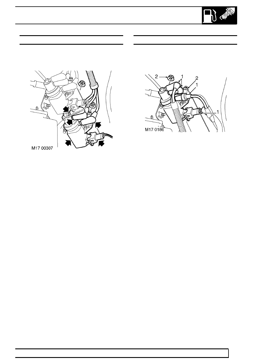
This system features twin modulators mounted one above the other on a metal plate located on the inner wing at
the RH side of the engine. The modulators are electrically controlled by the engine management system and are
used to modulate a vacuum source to the EGR valve and a supplementary Inlet Throttle (ILT) valve; the two
valves are controlled to operate in tandem. The ILT valve vacuum pot is mounted adjacent to the EGR valve
housing and has a linkage which connects to a butterfly valve mounted in front of the EGR valve at the air intake
manifold.
The modulator operations are electrically controlled by signals from the engine management system which
determines the required volume of exhaust gas needed in response to inputs relating to air flow, engine operating
conditions and ambient parameters such as temperature and altitude. The engine management ECM switches on
the circuit by completing the path to ground, operating the vacuum modulators.
Pre EU3 models: The exhaust gases are routed from the exhaust manifold through a shaped metal pipe which
connects to the underside of the EGR valve. The pipe is held securely in position to the front of the engine cylinder
head using a metal clamp bracket. The EGR pipe is attached to a mating port at the front end of the exhaust
manifold using two Allen screws and at the EGR valve assembly by a metal band clamp. The two Allen screws
fixing the EGR pipe to the exhaust manifold should be replaced every time the EGR pipe is removed.
CAUTION: Extreme care should be exercised when removing and refitting the EGR pipe to avoid
damage.
EU3 models: The exhaust gases are routed from the exhaust manifold through the EGR cooler to the underside
of the EGR valve. The EGR cooler is bolted to the front of the engine cylinder head. An EGR pipe connects the
EGR cooler to the exhaust manifold and is secured by two Allen screws. The two Allen screws fixing the EGR pipe
to the exhaust manifold should be replaced every time the EGR pipe is removed. A second pipe connects the
EGR cooler to the EGR valve; this pipe is secured to the EGR valve by a clip, and to the cooler by two Allen
screws.
CAUTION: Extreme care should be exercised when removing and refitting the EGR pipe to avoid
damage. When refitting the EGR cooler, always tighten the pipe connections BEFORE tightening
the bolts securing the cooler to the cylinder head.
When a vacuum is applied to the EGR suction port, it causes a spindle with sealing disc (EGR valve) to be raised,
opening the port at the EGR pipe to allow the recirculated exhaust gas to pass through into the inlet manifold. The
valve is spring loaded so that when the vacuum is removed from the suction port, the valve returns to its rest
position to tightly close the exhaust gas port.
A vacuum is simultaneously applied to the inlet throttle (ILT) valve suction port which causes the butterfly valve in
the inlet manifold to close by means of a spindle and lever mechanism. Closing the butterfly valve limits the supply
of fresh intercooled air entering the inlet manifold and causes a depression within the inlet manifold to create a
greater suction at the open port to the EGR delivery pipe. In this condition a greater mass of recirculated exhaust
gas is drawn into the inlet manifold for use in the combustion process. When the vacuum is released from the ILT
valve suction port a spring returns the butterfly valve to its fully open position.
By controlling the quantities of recirculated exhaust gas and fresh intake air available in the inlet manifold, the
optimum mix for the prevailing engine operating conditions can be maintained which ensures the intake gas to the
combustion chambers will have burning rate properties which will reduce the NO
2
emissions to an acceptable
level. Normally, full recirculation is only applicable when the NO
2
emissions are most prevalent.

EMISSION CONTROL
1
REPAIR
VALVE - EGR - NON EU3 MODELS
Service repair no - 17.45.01
Remove
1. Disconnect battery negative lead.
2. Remove 3 bolts and remove engine acoustic
cover.
3. Remove cooling fan. See COOLING SYSTEM,
Repair.
4. Remove battery cover.
5. Disconnect battery negative lead.
6. Disconnect vacuum hose from EGR valve
7. Loosen clip screw and release air intake from
EGR valve.
8. Remove 4 bolts, release EGR valve from inlet
manifold and discard gasket.
9. Remove 2 bolts and release EGR valve clip from
cylinder head.
10. Remove and discard 2 Allen screws securing
EGR valve pipe to exhaust manifold.
11. Remove EGR valve assembly.
12. Remove clip and remove pipe from EGR valve.
Refit
13. Clean EGR valve and mating face on pipe.
14. Position pipe to EGR valve, fit retaining clip and
finger tighten bolt.
15. Clean inlet manifold face.
16. Position EGR valve to inlet manifold using new
gasket and tighten bolts to 10 Nm (7lbf.ft).
17. Position air intake hose and tighten clip screw.
18. Position EGR pipe bracket, fit bolts and finger
tighten.
19. Position EGR valve pipe to exhaust manifold and
finger tighten allen screws
20. Tighten EGR valve clip to 5 Nm (3 lbf.ft).
21. Tighten EGR pipe bracket bolts to 10 Nm (7
lbf.ft).
22. Tighten 2 Allen screws to 10 Nm (7 lbf.ft).
23. Connect vacuum hose to EGR valve.
24. Fit cooling fan. See COOLING SYSTEM,
Repair.
25. Fit engine acoustic cover.
26. Reconnect battery negative lead.
27. Fit battery cover.

17
EMISSION CONTROL
2
REPAIR
VALVE - EGR - EU3 MODELS
Service repair no - 17.45.01
Remove
1. Release turnbuckles and remove battery cover.
2. Disconnect battery earth lead.
3. Remove 3 bolts and remove engine acoustic
cover.
4. Remove cooling fan coupling. See COOLING
SYSTEM, Repair.
5. Disconnect vacuum hose(s) from EGR valve.
6. Loosen screw and disconnect air intake hose
from EGR valve.
7. Remove screw and remove clamp securing EGR
pipe to EGR valve.
8. Remove 4 bolts securing EGR valve, remove
valve and discard gasket.
9. Discard EGR pipe gasket.
Refit
10. Clean EGR valve and mating faces.
11. Fit new gasket to EGR pipe.
12. Using new gasket, position EGR valve to inlet
manifold fit bolts and tighten to 10 Nm (7 lbf.ft).
13. Fit EGR pipe clamp and tighten screw to 6 Nm
(4.4 lbf.ft).
14. Connect air intake hose to EGR valve and
tighten clip.
15. Connect vacuum hoses to EGR valve.
16. Fit cooling fan coupling. See COOLING
SYSTEM, Repair.
17. Fit engine acoustic cover and tighten bolts to 10
Nm (7 lbf.ft).
18. Connect battery earth lead.
19. Fit battery cover and secure the fixings.
EMISSION CONTROL
3
REPAIR
INLET THROTTLE (ILT) MODULATOR
Service repair no - 17.45.03
Remove
1. Identify the fitted positions of the 3 vacuum
pipes, then disconnect from the ILT modulator
valve.
2. Disconnect multiplug from ILT modulator.
3. Remove 2 nuts securing modulator and remove
ILT modulator from its moutings.
Refit
4. Fit ILT modulator to its mountings, fit the nuts
and tighten to 10 Nm (7 lbf.ft).
5. Connect vacuum pipes to the positions identified
during removal.
6. Connect multiplug to ILT modulator.
SOLENOID - VALVE - EGR
Service repair no - 17.45.04
Remove
1. Disconnect vacuum pipes and multiplug from
EGR solenoid.
2. Remove 2 nuts and remove EGR solenoid.
Refit
3. Position EGR solenoid and tighten securing
nuts.
4. Connect vacuum hoses and multiplug.
Нет комментариевНе стесняйтесь поделиться с нами вашим ценным мнением.
Текст