Defender. Manual — part 69
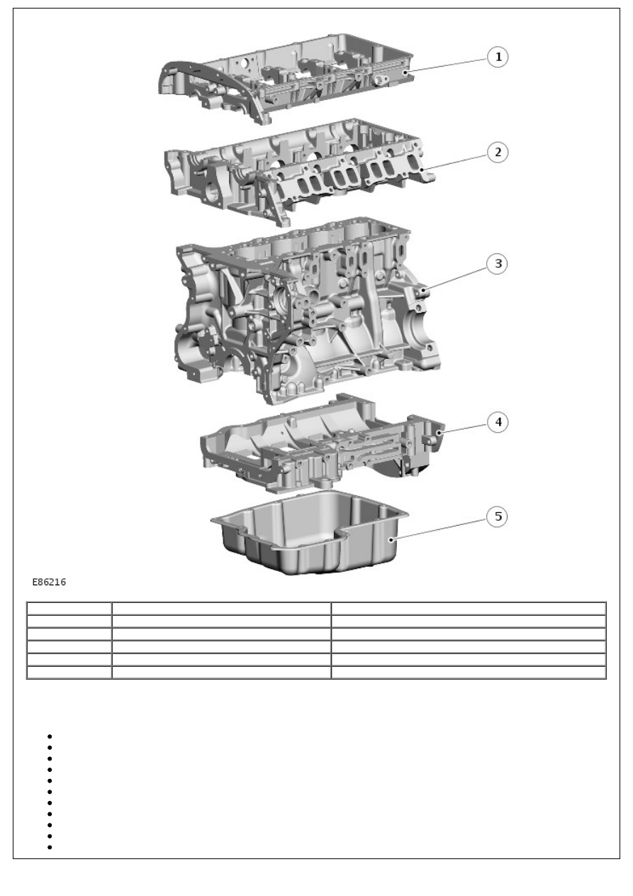
Item
Part Number
Description
1
-
Camshaft carrier
2
-
Cylinder head
3
-
Cylinder block
4
-
Ladder frame
5
-
Oil pan
TECHNICAL FEATURES AND DATA
The technical features include:
A 4 cylinder liquid cooled CGI cylinder block
A light, high strength, aluminum cylinder head
Four-valve technology with centrally arranged fuel injectors
Steel roller rockers with hydraulic lash adjusters
Variable geometry turbocharger
Common rail direct fuel injection system
High pressure injection fuel pump
Gallery cooled pistons with a central crown bowl
Electronically controlled water cooled EGR valve
Exhaust re-treatment by means of a diesel specific oxidation catalytic converter
Cooling fan with electro-viscous clutch drive
Technical Data
Description
Specifications
Cubic capacity
2,402 ccm
Stroke
94.6 mm
Bore
89.9 mm
Compression ratio
19:1
Firing order
1-3-4-2
Idle speed
900 rpm
Max. power output
90 kW (122 PS) at 3,500 rpm
Max. torque
360 Nm at 2,000 rpm
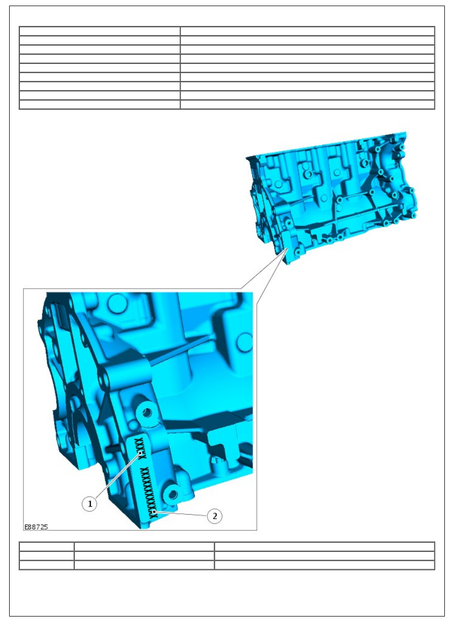
Engine Identification Code
Item
Part Number
Description
1
-
Engine code
2
-
Engine serial number
The engine serial number (12 digits) and engine code (5 digits) are stamped on the exhaust side of the cylinder block,
parallel to the transmission clutch housing.
Engine Identification Plate
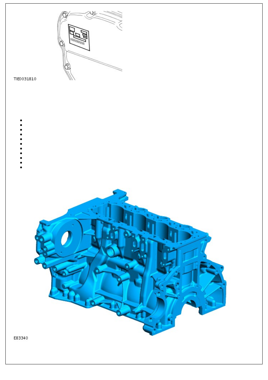
The engine identification plate is located on the cover of the timing cover. It contains the date and time of manufacture
and the engine part number.
CYLINDER BLOCK COMPONENTS
The main cylinder block components are:
The cylinder block
Piston cooling jets
Rear crankshaft oil seal and retainer
Connecting rods and pistons
Crankshaft Position (CKP) sensor
Starter motor
Generator
Coolant and vacuum pump
Power steering pump
High-pressure fuel pump
Coolant distribution manifold
Cylinder Block
The cylinders and crankcase are contained in the cylinder block, which is of single cast CGI construction with a hollow
beam structure. With this type of construction less material is required than for a conventional cast iron block,
therefore, reducing engine weight and length.
The cylinder bores are machined directly in the block.
Three different bore diameters are used in production to ensure very precise adjustment of the clearance between the
pistons and cylinders.
A turbocharger oil feed filter is located at number 1 journal to prevent debris from entering the turbocharger and
damaging the bearings.
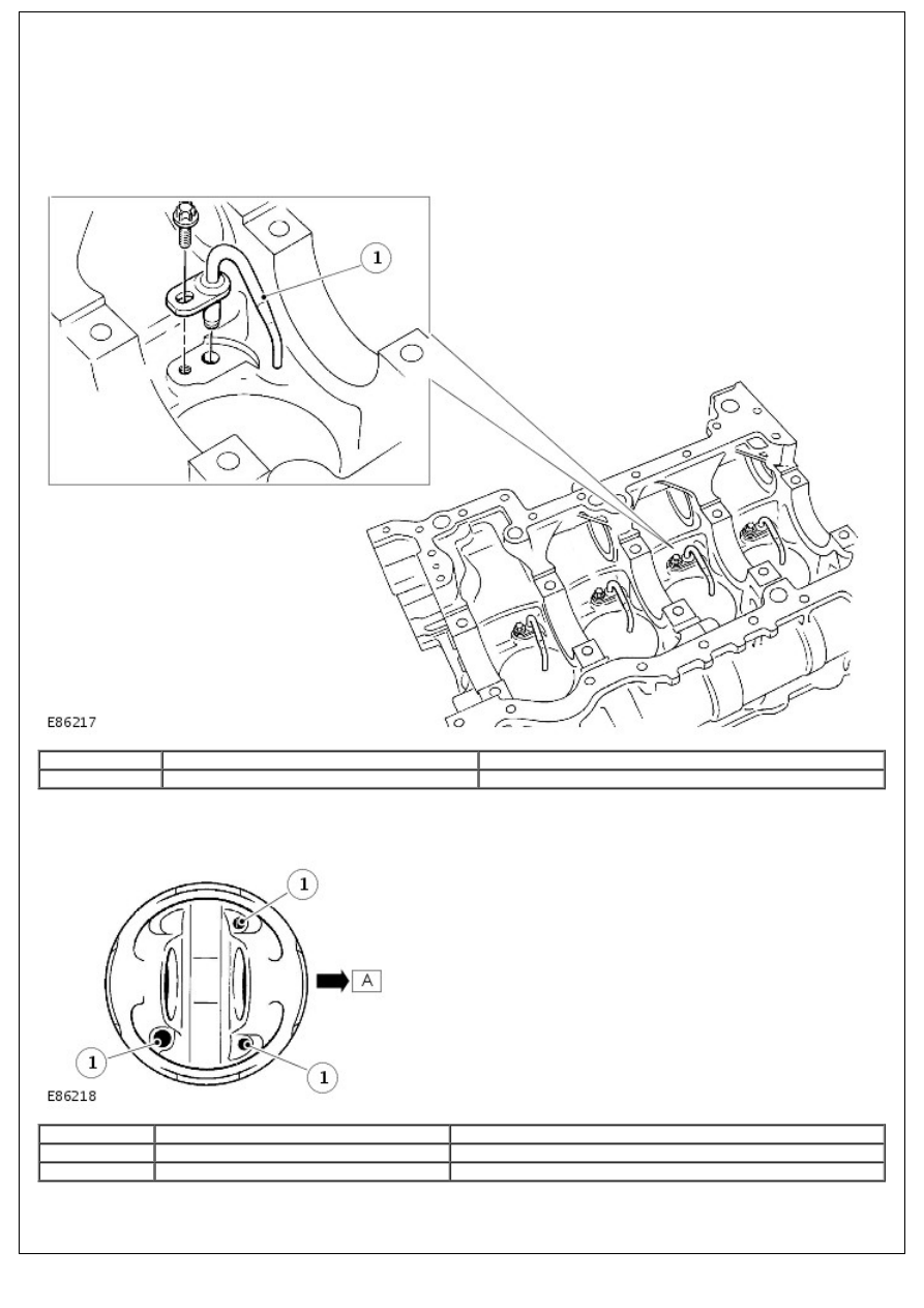
Piston Cooling Jets
Item
Part Number
Description
1
-
Piston cooling jet
Jets located in the cylinder block provide piston and piston pin lubrication and cooling. These jets spray oil on to the
inside of the piston, the oil then flows through an internal wave shaped oil cooling channel to help cool each piston
crown.
Item
Part Number
Description
A
-
Front of the engine
1
-
Oil cooling channels
Lubrication oil is distributed through the cylinder block, via the main oil gallery and channels bored in the block, to all
critical moving parts. These channels divert oil to the main and big-end bearings via holes machined into the crankshaft.
Нет комментариевНе стесняйтесь поделиться с нами вашим ценным мнением.
Текст