Defender. Manual — part 222
Generator and Regulator - 2.4L Duratorq-TDCi HPCR (103kW/140PS) -
Puma -
Description
Nm
lb-ft
Generator battery positive cable nut
8
6
Generator bolts
48
35
Generator and Regulator - 2.4L Duratorq-TDCi HPCR (103kW/140PS) -
Puma - Generator2.4L Duratorq-TDCi HPCR (103kW/140PS) - Puma
Description and Operation
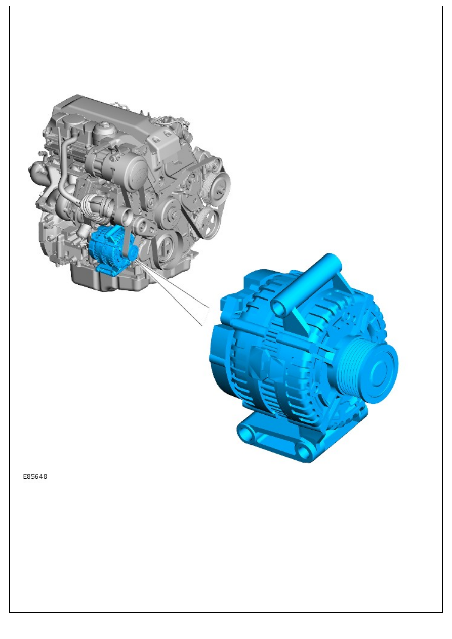
COMPONENT LOCATION
OVERVIEW
The generator is located at the front RH side of the engine. The generator has an output of 85/150 Amps and is
manufactured by Denso. An eight-ribbed polyvee belt drives the generator pulley, which in turn is driven from the engine
crankshaft pulley.
The generator pulley incorporates a one-way clutch mechanism, which allows the pulley to free wheel, reducing the
amount of inertia applied to the engine during deceleration (coast). The generator comprises a stator, a rotor, a rectifier
pack and a regulator.
The generator is connected to ground via its mountings.
The rotor comprises a field winding, wound around an iron core and mounted on a shaft. The iron core has extensions
at each end, which form North and South poles as current flows through the field winding. The rotor is located inside the
stator and is mounted on bearings for smooth running and to support the rotor due to the high side loading applied by
the drive belt tension.
The stator has three sets of coils made from copper wire. The three coil windings are connected in a 'star' connection,
where one end of the winding is connected to the other two windings. The output current is supplied from the opposite
end of each winding. Rotation of the rotor causes ac current to be produced in the coils.
The rectifier converts the ac current produced in the stator coils into dc (rectified) current required by the vehicle
electrical system. The rectifier comprises semi-conductor diodes mounted on a heatsink to dissipate heat. An equal
number of the diodes are on the negative and positive side. An additional diode in the regulator controls feedback
through the battery voltage signal line. The rectifier also prevents current flow from the battery to the generator when
the output voltage is less than the battery voltage.
The 'smart' regulator controls the output voltage from the generator to protect the battery; at low temperatures battery
charge acceptance is very poor so the voltage needs to be high to maximise any re-chargeability, but at high
temperatures the charge voltage must be restricted to prevent excessive gassing with consequent water loss. The
Engine Management System (EMS), which controls the regulator, will calculate the voltage set point required for the
ensuing conditions. The 'traditional' regulator controls voltage against generator temperature, which means the battery
temperature will lag a long way behind so there will be significant periods of operation when battery charging is
compromised. With this system, the EMS can set the voltage by inferring the battery temperature from information
received from it's various sensors, hence voltage will accurately follow the battery's needs.
The regulator has transistors, which rapidly switch on and off to regulate the voltage output according to the voltage
sensed internally. The regulator also provides a PWM signal output to the ECM, which uses the signal to adjust the idle
speed under varying electrical loads.
Initially, the ignition switch supply provides an excitation current to the rotor at low generator speeds via brushes, which
contact slip rings at the end of the rotor shaft. As the generator speed increases the generator becomes self-exciting.
The charge warning lamp function is transmitted to the EMS and then on to the Controller Area Network (CAN) bus to
the instrument cluster.
LOAD MANAGEMENT SYSTEM
The load management system comprises software resident in the Automatic Temperature Control (ATC) module .For
additional information, refer to:Control Components (412-04 Control Components, Description and Operation). Its
purpose is to protect battery state-of-charge during abnormal usage of the vehicle. The system will request the Media
Orientated System Transport (MOST) ring and the air suspension to go into 'power save' mode, and will modulate
features such as seat heating and screen heating to prevent the battery being dragged down to a point where the car
becomes un-operational. A 'WARNING - LOW BATTERY' message will be displayed in the message center.
Generator and Regulator - 2.4L Duratorq-TDCi HPCR (103kW/140PS) -
Puma - Generator
Removal and Installation
Removal
1. Disconnect the battery ground cable.
For additional information, refer to:
Battery Disconnect and
Connect
(414-01 Battery, Mounting and Cables, General
Procedures).
2. Remove the accessory drive belt.
For additional information, refer to:
Accessory Drive Belt
(303-05 Accessory Drive - 2.4L Duratorq-TDCi HPCR
(103kW/140PS) - Puma, Removal and Installation).
3. Remove the air cleaner outlet pipe.
For additional information, refer to:
Air Cleaner Outlet Pipe
(303-12 Intake Air Distribution and Filtering - 2.4L Duratorq-
TDCi HPCR (103kW/140PS) - Puma, Removal and
Installation).
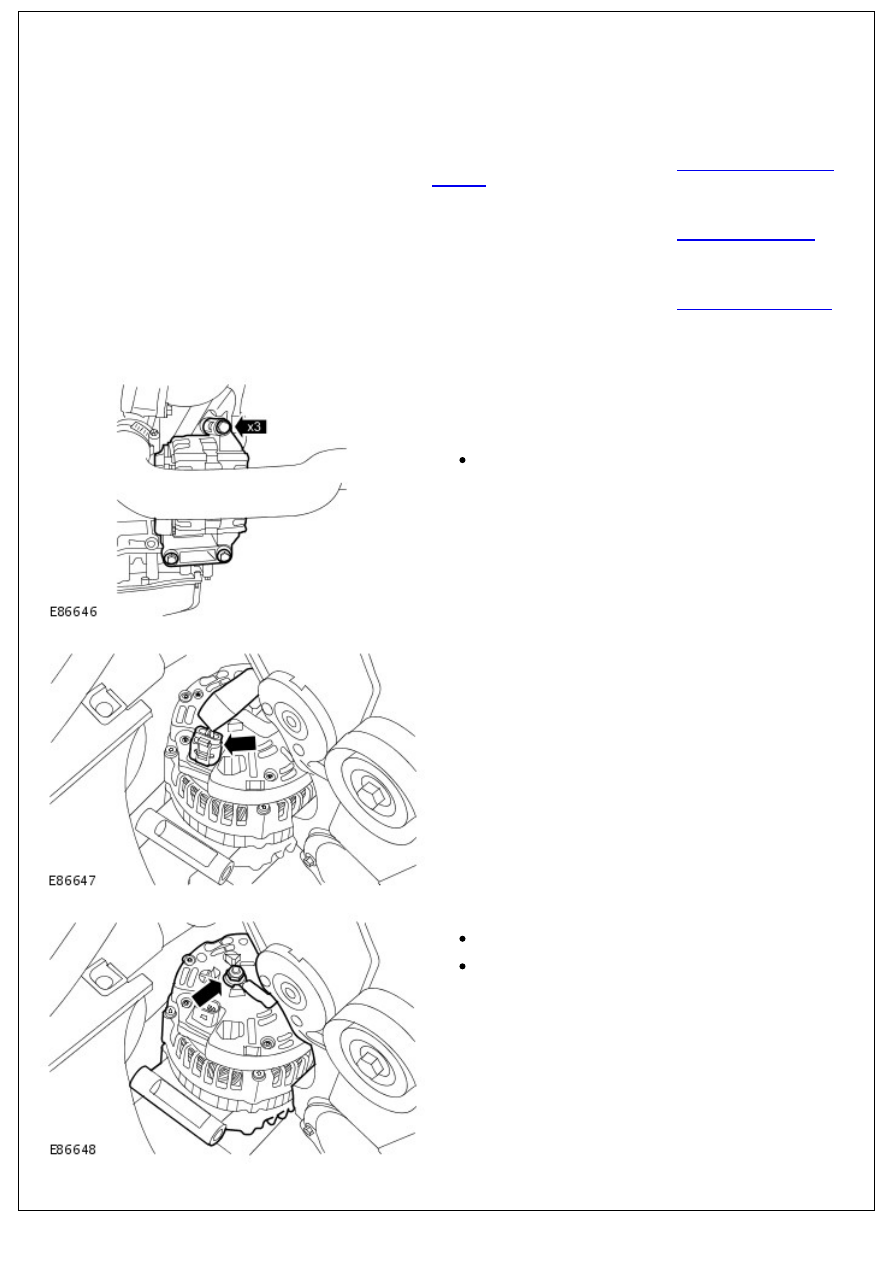
4. NOTE: The generator upper bolt can only be removed when
the generator has been released from the accessory drive
component bracket.
Release the generator.
Remove the 3 bolts.
5. Disconnect the generator electrical connector.
6. Remove the generator.
Remove the battery positive cable nut.
Release the battery positive cable.
Installation
Нет комментариевНе стесняйтесь поделиться с нами вашим ценным мнением.
Текст