Defender. Manual — part 56
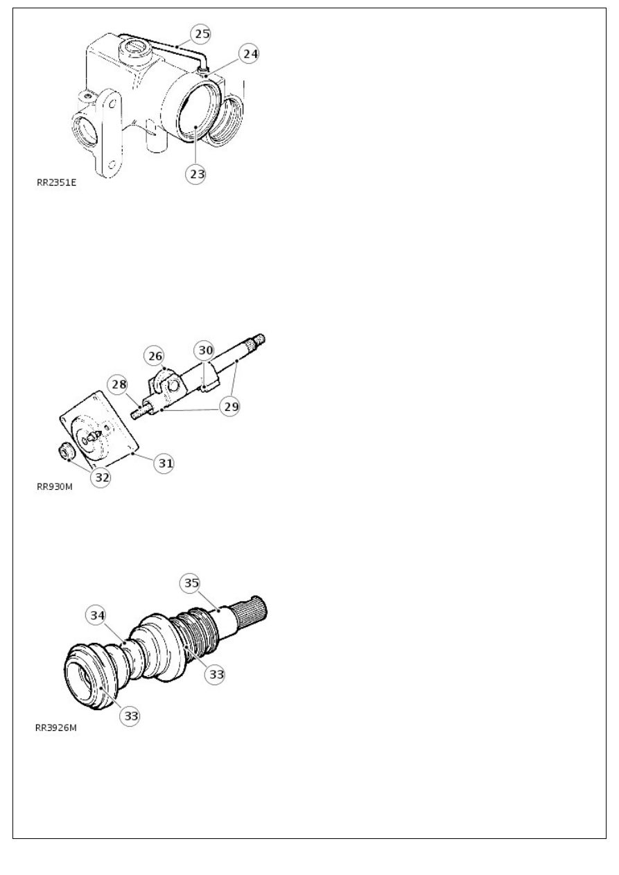
25. Fit a new feed tube if damaged. Tighten union to 22 Nm
(16 lbf/ft).
26. Check there is no side play on roller.
27. If side play on roller exists fit a new sector shaft.
28. Check condition of adjuster screw threads. Check adjuster
end float. Fit new adjuster if end float exceeds 0.15 mm.
29. Examine bearing areas on shaft for excessive wear.
30. Examine gear teeth for uneven or excessive wear.
31. Inspect cover and bearing. If worn or damaged, fit a new
steering gear.
32. The locknut is also a fluid seal. Fit new nut during
assembly.
33. Examine bearing areas for wear. The areas must be
smooth and not indented.
34. Examine worm track which must be smooth and not
indented.
35. NOTE: Any sign of wear makes it essential to fit new
valve and worm assembly.
Check for wear on torsion bar assembly pin. No free
movement should exist between input shaft and torsion bar
or between torsion bar and worm.
36. Examine valve rings for cuts , scratches and grooves. The
valve rings should be free to rotate in grooves. Renew the
valve and worm assembly if any faults are found.
37. Examine ball races and cups for wear and general
condition.
38. If ball cage has worn against bearing cup, fit replacements.
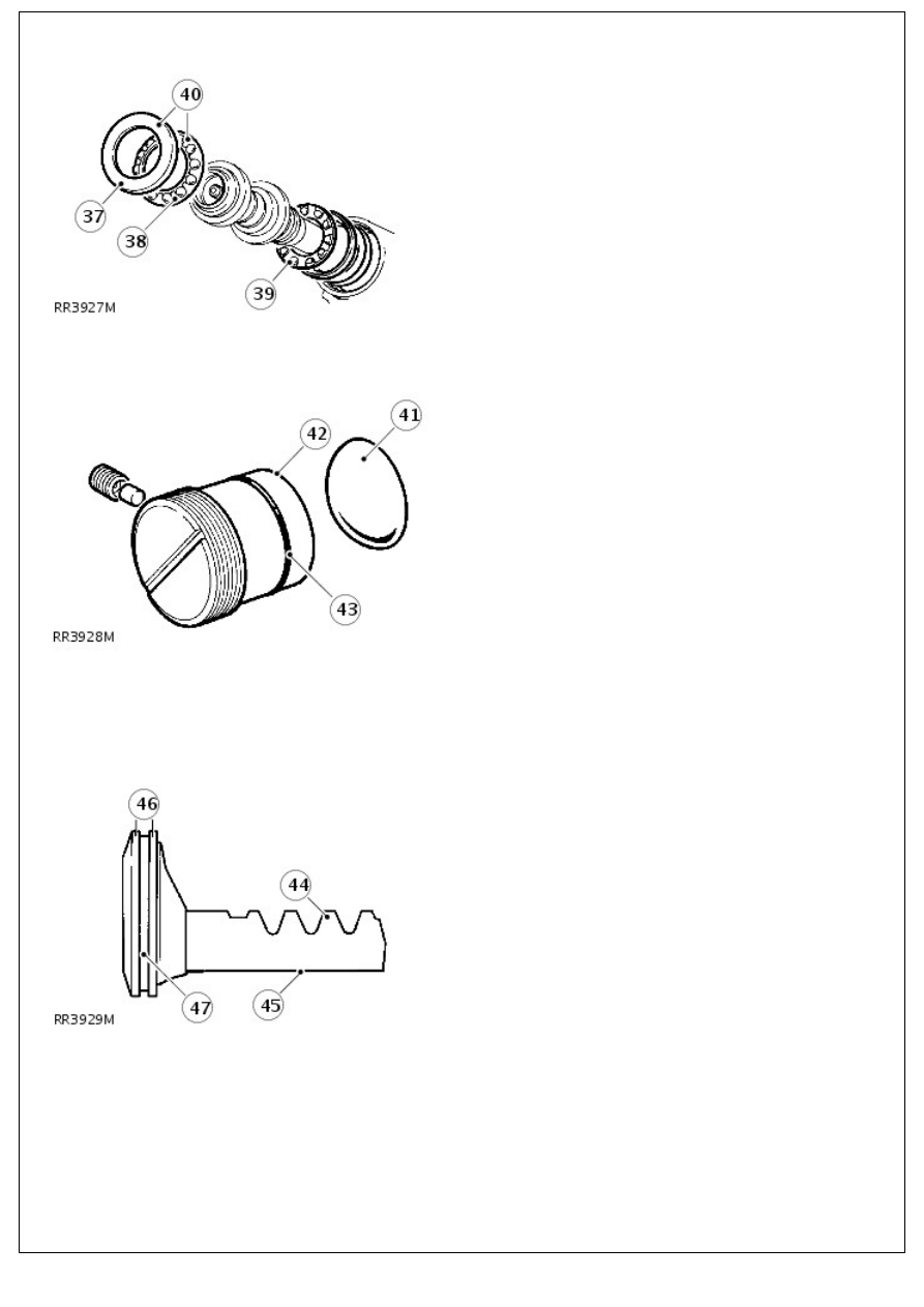
39. Bearing balls must be retained by cage.
40. Bearing and cage repair is carried out by complete
replacement of assembly.
41. Examine thrust pad for scores.
42. Examine adjuster for wear in pad seat.
43. Fit new sealing ring to rack adjuster.
44. Examine for excessive wear on rack teeth.
45. Ensure thrust pad bearing surface is free from scores and
wear.
46. Ensure piston outer diameters are free from burrs and
damage.
47. Examine seal and ring groove for scores and damage.
Assembly
1. Fit new ring to piston. Warm nylon seal and fit to piston.
2. Slide piston assembly into cylinder with rack tube outwards.
• NOTE: When fitting replacement oil seals lubricate with recommended fluid and ensure absolute cleanliness.
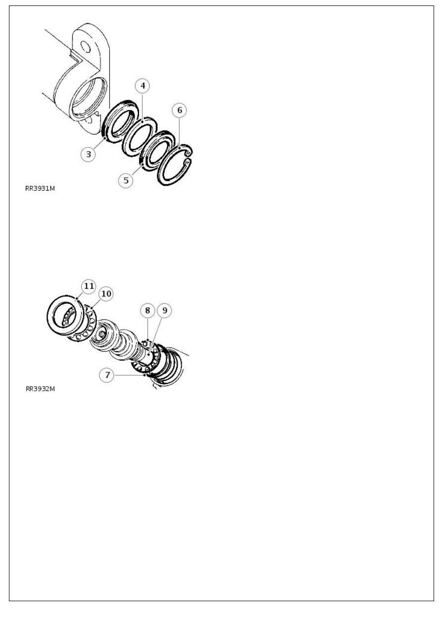
3. Fit oil seal, lip side first.
4. Fit extrusion washer.
5. Fit dust seal, lipped side last.
6. Fit circlip.
6. Fit circlip.
7. Refit original shims and inner bearing cup. Use Petroleum
Jelly to aid assembly.
• NOTE: If original shims are not used, fit shims of 0.76 mm thickness.
8. Fit inner cage and bearings assembly.
9. Fit valve and worm assembly.
10. Fit outer cage and bearings assembly.
11. Fit outer bearing cup.
12. Fit new worm adjuster sealing ring.
13. Loosely screw adjuster into casing.
14. Fit locknut, do not tighten.
15. Turn in worm adjuster until end float is almost eliminated.
Ensure bearing cages are seated correctly.
16. Measure maximum rolling torque of valve and worm
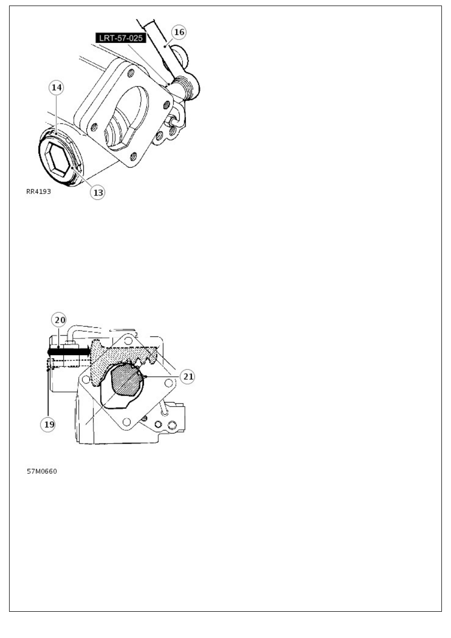
16. Measure maximum rolling torque of valve and worm
assembly, using a torque wrench and spline socket LRT-57-
025.
17. Turn in worm adjuster while rotating shaft to increase
figure measured to 0.56 Nm.
18. Back off worm adjuster ! turn. Turn in worm adjuster to
increase reading by 0.21 - 0.34 Nm with locknut tight, 100
Nm (74 lbf/ft). Use worm adjusting wrench LRT-57-006 and
locknut wrench LRT-57-028.
19. Screw slave bolt into piston to aid assembly.
20. Fit piston and rack so piston is 70 mm (2.75 in) from outer
end of bore.
21. Fit sector shaft using seal saver LRT-57-021. Align roller
with cut out in casing as shown. Push in sector shaft while
rotating input shaft to allow sector roller to engage worm.
22. Fit rack adjuster and thrust pad to engage rack. Back off
half turn on adjuster.
23. Loosely fit new nylon pad and adjuster set screw
Нет комментариевНе стесняйтесь поделиться с нами вашим ценным мнением.
Текст