Defender. Manual — part 139
Intake Air Distribution and Filtering - 2.4L Duratorq-TDCi HPCR
(103kW/140PS) - Puma - Intake Air Distribution and Filtering
Description and Operation
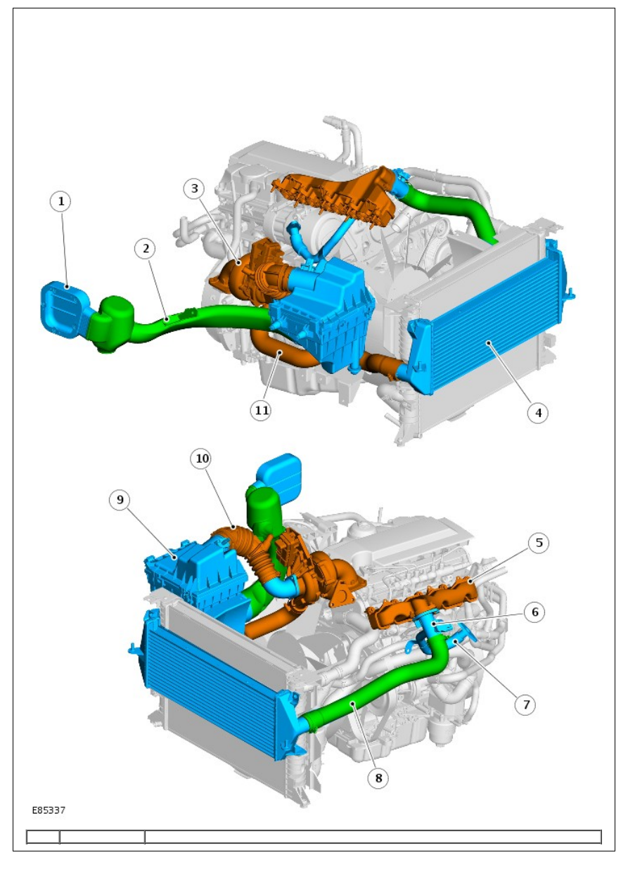
COMPONENT LOCATION
Item
Part Number
Description

1
-
Air intake
2
-
Dirty air duct
3
-
Turbocharger
4
-
Charge air cooler
5
-
Air intake manifold
6
-
Mass airflow sensor housing and exhaust gas recirculation (EGR) connection
7
-
EGR connection tube
8
-
Charge air cooler to intake manifold tube
9
-
Air cleaner box
10
-
Air cleaner box to turbo tube
11
-
Turbo charger to charge air cooler tube
OVERVIEW
Air is drawn in from the vehicle exterior via the right-hand (RH) wing mounted intake duct, along the inside of the wing
to the air cleaner box intake. Once the air has passed through the air cleaner it is drawn along a duct to the
turbocharger. From the turbo charger the air is forced through the charge air cooler up to the intake manifold.
AIR CLEANER BOX
The air cleaner box is located on the inside of the right hand fender. The air cleaner box is attached to the vehicle by
four rubber mounts, 2 on the side to the inside of the inner fender and two on the base of the box. The box contains a
replaceable paper filter element.
CHARGE AIR COOLER
The charge air cooler is located in front of the radiator and is secured to the radiator by 2 bolts at the top and 2 location
points at the bottom. Air is forced through the charge air cooler by the turbocharger. Cooling the air makes it more
dense improving combustion.
Intake Air Distribution and Filtering - 2.4L Duratorq-TDCi HPCR
(103kW/140PS) - Puma - Intake Air Distribution and Filtering
Diagnosis and Testing
Overview
For information on description and operation:
REFER to:
Intake Air Distribution and Filtering
(303-12 Intake Air Distribution and Filtering - 2.4L Duratorq-TDCi HPCR
(103kW/140PS) - Puma, Description and Operation).
Inspection and Verification
1. 1. Verify the customer concern.
2. 2. Visually inspect for obvious signs of mechanical or electrical damage.
Visual Inspection Chart
Mechanical
Electrical
Hoses and ducts: condition and fitment
Air cleaner element condition and fitment
Restricted air intake
Vacuum hoses condition and fitment
Pipework to/from turbocharger: condition and
fitment
Turbocharger: condition and fitment
Charge air cooler
Fuse(s)
Wiring harness(es)
Loose or corroded electrical connector(s)
Mass air flow (MAF) sensor
Manifold absolute pressure/temperature (MAPT)
sensors
Intake air temperature (IAT) sensor
- IAT sensor 1 is part of the MAF sensor
3. 3. If an obvious cause for an observed or reported concern is found, correct the cause (if possible) before
proceeding to the next step.
4. 4. Use the approved diagnostic system or a scan tool to retrieve any diagnostic trouble codes (DTCs) before
moving onto the symptom chart or DTC index.
Make sure that all DTCs are cleared following rectification.
Symptom Chart
Symptom
Possible causes
Action
Vehicle does
not
start/hard
starting
Restricted/blocked air
intake
Restricted/blocked air
cleaner element
Check the intake air system for blockages or restriction. Rectify as
necessary.
Poor
performance
Intake air system fault
Turbocharger fault(s)
Exhaust gas
recirculation (EGR)
valve fault
Low fuel pressure
Restricted exhaust
system
Check the intake air system for blockages or restriction. Rectify as
necessary. Check for DTCs indicating a turbocharger, EGR valve or fuel
pressure fault. Rectify as necessary. Check the exhaust system for evidence
of damage or restriction. Rectify as necessary.
Excessive
intake noise
Intake air leak after
the turbocharger
Intake pipe
disconnected/damaged
after the air cleaner
Air cleaner assembly
incorrectly
assembled/damaged
Check the intake air system for loose or disconnected hoses or ducts. Check
the hoses and ducts for damage, splits, etc. Rectify as necessary.
DTC Index
• NOTE: If a control module or component is suspect and the vehicle remains under manufacturer warranty, refer to the
Warranty Policy and Procedures manual (section B1.2), or determine if any prior approval program is in operation,
before the replacement of a component.
• NOTE: Generic scan tools may not read the codes listed, or may read only 5-digit codes. Match the 5 digits from the
scan tool to the first 5 digits of the 7-digit code listed to identify the fault (the last 2 digits give extra information read
by the manufacturer-approved diagnostic system).
• NOTE: When performing voltage or resistance tests, always use a digital multimeter (DMM) accurate to three decimal
places, and with an up-to-date calibration certificate. When testing resistance always take the resistance of the DMM
leads into account.
• NOTE: Check and rectify basic faults before beginning diagnostic routines involving pinpoint tests.
• NOTE: Inspect connectors for signs of water ingress, and pins for damage and/or corrosion.
• NOTE: If DTCs are recorded and, after performing the pinpoint tests, a fault is not present, an intermittent concern
may be the cause. Always check for loose connections and corroded terminals.
• NOTE: For a full list of engine control module (ECM) DTCs:
REFER to:
Electronic Engine Controls
(303-14 Electronic Engine Controls - 2.4L Duratorq-TDCi HPCR (103kW/140PS) -
Puma, Diagnosis and Testing).
DTC
Description
Possible causes
Action
P00952F Intake air temperature
(IAT) sensor 2 circuit -
signal erratic
• NOTE: The IAT sensor 2 is
part of the manifold absolute
pressure temperature
(MAPT) sensor
IAT sensor 2 circuit:
open circuit
IAT sensor 2: short
circuit to power
IAT sensor 2: short
circuit to ground
IAT sensor 2 fault
Check the IAT sensor 2 and circuits. Refer to the
electrical guides. Install a new MAPT sensor if necessary.
REFER to:
Manifold Absolute Pressure and Temperature
(MAPT) Sensor
(303-14 Electronic Engine Controls - 2.4L
Duratorq-TDCi HPCR (103kW/140PS) - Puma, Removal
and Installation).
Clear the DTCs and test for normal operation.
P009511 Intake air temperature
(IAT) sensor 2 circuit -
circuit short to ground
• NOTE: The IAT sensor 2 is
part of the manifold absolute
pressure temperature
(MAPT) sensor
IAT sensor 2: short
circuit to ground
IAT sensor 2 fault
Check the IAT sensor 2 and circuits. Refer to the
electrical guides. Install a new MAPT sensor if necessary.
REFER to:
Manifold Absolute Pressure and Temperature
(MAPT) Sensor
(303-14 Electronic Engine Controls - 2.4L
Duratorq-TDCi HPCR (103kW/140PS) - Puma, Removal
and Installation).
Clear the DTCs and test for normal operation.
P009515 Intake air temperature
(IAT) sensor 2 circuit -
circuit short to battery
or open
• NOTE: The IAT sensor 2 is
part of the manifold absolute
pressure temperature
(MAPT) sensor
IAT sensor 2: open
circuit
IAT sensor 2: short
circuit to power
IAT sensor 2 fault
Check the IAT sensor 2 and circuits. Refer to the
electrical guides. Install a new MAPT sensor if necessary.
REFER to:
Manifold Absolute Pressure and Temperature
(MAPT) Sensor
(303-14 Electronic Engine Controls - 2.4L
Duratorq-TDCi HPCR (103kW/140PS) - Puma, Removal
and Installation).
Clear the DTCs and test for normal operation.
P010029 Mass or volume air
flow A circuit - signal
invalid
Restricted air intake
path
Check for leak
between mass air
flow (MAF) sensor
and turbocharger
MAF sensor fault
Turbocharger fault
Exhaust gas
recirculation (EGR)
valve fault
Check the intake air system for leaks, restrictions, etc.
Check for related DTCs. Rectify as necessary. Clear the
DTCs and test for normal operation.
P010036 Mass or volume air
flow A circuit - signal
frequency too low
Mass air flow (MAF)
sensor circuit: short
circuit to ground
MAF sensor circuit:
short circuit to power
MAF sensor circuit:
open circuit
MAF sensor fault
Check the MAF sensor and circuit. Refer to the electrical
guides. Install a new MAF sensor if necessary.
REFER to:
Mass Air Flow (MAF) Sensor
(303-14
Electronic Engine Controls - 2.4L Duratorq-TDCi HPCR
(103kW/140PS) - Puma, Removal and Installation).
Clear the DTCs and test for normal operation.
P010037 Mass or volume air
flow A circuit - signal
frequency too high
Mass air flow (MAF)
sensor circuit: short
circuit to ground
MAF sensor circuit:
short circuit to power
MAF sensor circuit:
open circuit
MAF sensor fault
Check the MAF sensor and circuit. Refer to the electrical
guides. Install a new MAF sensor if necessary.
REFER to:
Mass Air Flow (MAF) Sensor
(303-14
Electronic Engine Controls - 2.4L Duratorq-TDCi HPCR
(103kW/140PS) - Puma, Removal and Installation).
Clear the DTCs and test for normal operation.
Нет комментариевНе стесняйтесь поделиться с нами вашим ценным мнением.
Текст