Defender. Manual — part 228
Content not found
Exterior Lighting - Exterior Lighting
Description and Operation
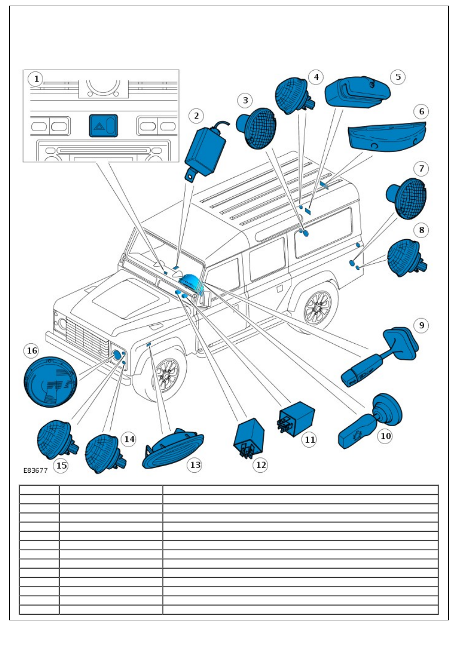
COMPONENT LOCATION - MODELS FROM 2007MY (NOT SVX (60TH ANNIVERSARY) MODEL)
Item
Part Number
Description
1
-
Hazard flasher switch
2
-
Fog lamp control module
3
-
Rear fog lamp
4
-
Rear tail/Stop lamp
5
-
License plate lamp
6
-
High mounted stop lamp
7
-
Reverse lamp
8
-
Rear turn signal indicator lamp
9
-
Steering column multifunction switch
10
-
Lighting control switch
11
-
Headlamp relay
12
-
Hazard flasher relay
13
-
Side turn signal indicator lamp
14
-
Front turn signal indicator lamp
15
-
Side lamp
16
-
Headlamp
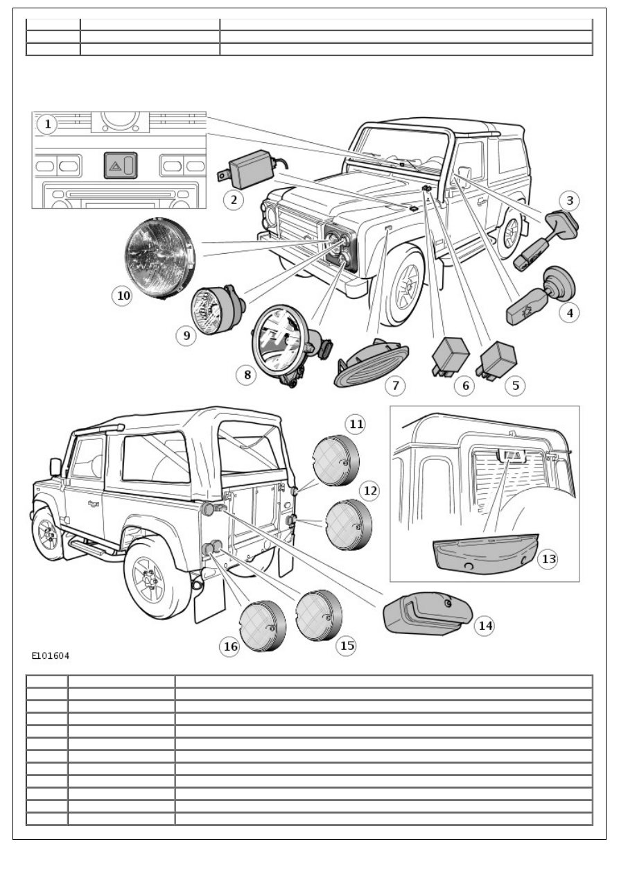
COMPONENT LOCATION - SVX (60TH ANNIVERSARY) MODEL
• NOTE: 90 model shown, 110 model similar
Item
Part Number
Description
1
-
Hazard flasher switch
2
-
Fog lamp control module
3
-
Steering column multifunction switch
4
-
Lighting control switch
5
-
Headlamp relay
6
-
Hazard flasher relay
7
-
Side turn signal indicator lamp (2 off)
8
-
Auxiliary high beam lamp (2 off)
9
-
Front turn signal indicator lamp (2 off)
10
-
Headlamp - incorporating integral side lamp
11
-
Rear tail/Stop lamp (2 off)

12
-
Rear fog lamp or reverse lamp (depending on market)
13
-
High mounted stop lamp (Not 90 models)
14
-
Licence plate lamp
15
-
Rear fog lamp or reverse lamp (depending on market)
16
-
Rear turn signal indicator lamp (2 off)
OVERVIEW
Operation of the exterior lamps is controlled via the lighting control switch and the steering column multifunction switch.
The lighting control switch is a 3 way switch mounted on the left-hand (LH) side of the steering column. When pushed
forward to the first position the switch will provide a battery feed to the side lamps, tail lamps and number plate lamps
irrespective of ignition switch position. When pushed forward to the second position, the lighting control switch will also
provide a feed to the headlamp relay.
The steering column multifunction switch is mounted forward of the lighting control switch on the LH side of the steering
column and allows the driver to switch between headlamp high beam, low beam and flash operation. The steering
column multifunction switch is provided a feed by the headlamp relay, which becomes energized when the ignition
switch is turned to position II.
Where fitted, a 4 position rotary headlamp leveling switch is mounted on the instrument panel to allow the driver to
raise or lower headlamp alignment according to the load being carried in the vehicle. A motor mounted on the rear of
each headlamp adjusts the alignment of the headlamps in response to movements in switch position.
Operation of the turn signal indicator lamps is also controlled using the steering column multifunction switch. The
steering column multifunction switch is provided an ignition switch feed from the hazard flasher relay. When the switch
is moved to the left or right turn position, the switch contacts close and a feed is provided to the relevant turn signal
indicator lamps. A feed is also provided to the instrument cluster to illuminate the turn signal warning indicator.
The hazard flasher switch is located on the instrument panel and operates the LH and right-hand (RH) turn signal
indicator lamps simultaneously when pressed. The hazard flasher switch is provided a constant battery feed and will
operate the turn signal indicator lamps irrespective of ignition switch position. When pressed, the hazard flasher switch
also provides a feed to the instrument cluster to illuminate the hazard flasher warning indicator.
The stop lamps are controlled by the stop lamp switch, which is mounted on top of the brake pedal. When the brake
pedal is pressed the switch contacts close allowing an ignition switch feed to power the stop lamps.
The reverse lamp is controlled by the reverse gear switch, which is mounted on the transmission. When reverse gear is
selected the switch contacts close allowing an ignition switch feed to power the reverse lamp.
Operation of the rear fog lamp is controlled by the fog lamp control module, which is located beneath the RH front seat.
The control module is provided an ignition switch feed from the energized headlamp relay via the central junction box
(CJB). The control module monitors the condition of the fog lamp switch. When the switch is pressed, the switch
contacts close and a ground path is created. When the control module registers the ground path it provides a feed to the
rear fog lamp and the instrument cluster.
SVX (60th Anniversary) Model
The exterior lighting system on the 2008MY SVX model is as described above with the following differences:
light emitting diode (LED) rear lights
halogen headlamps with a complex surface reflector and integral side lamp
separate high beam driving lamps
new front turn signal indicator lamps.
DESCRIPTION - SVX (60TH ANNIVERSARY) MODEL
Headlamp
Нет комментариевНе стесняйтесь поделиться с нами вашим ценным мнением.
Текст