Defender. Manual — part 144
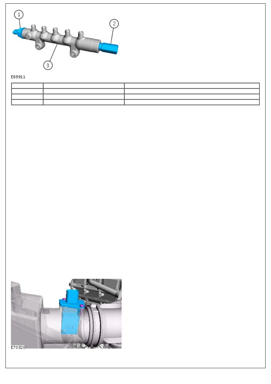
Item
Part Number
Description
1
-
Fuel pressure sensor
2
-
Pressure limiting valve
3
-
Fuel rail
The fuel rail pressure sensor is located forward end of the fuel rail. The fuel rail pressure sensor measures the pressure
of the fuel in the fuel rail. This input is then used by the ECM to control the amount of fuel delivered to the fuel rail.
FUEL RAIL PRESSURE RELIEF VALVE
The fuel rail pressure relief valve is located at the rear end of the fuel rail. To prevent damage to the high pressure fuel
system, the valve opens when the fuel pressure in the rail reaches approximately 2000 bar. The ECM detects the valve
opening and sends a malfunction indicator lamp (MIL) request to the instrument cluster.
Once the valve has been opened it needs to be replaced.
FUEL TEMPERATURE SENSOR
The fuel temperature sensor is located in the high pressure fuel pump.
The sensor is an NTC sensor which is connected to the ECM by two wires. The ECM fuel temperature sensor circuit
consists of an internal voltage divider circuit which incorporates an NTC thermistor. As the fuel temperature rises the
resistance through the sensor decreases. The output from the sensor is the change in voltage as the thermistor allows
more current to pass to earth relative to the temperature of the fuel.
The ECM monitors the fuel temperature constantly. If the fuel temperature exceeds 85°Celsius (185°F), the ECM invokes
an engine 'derate' strategy. This reduces the amount of fuel delivered to the injectors in order to allow the fuel to cool.
When this occurs, the driver may notice a loss of performance.
Further fuel cooling is available by a bi-metallic valve diverting fuel through the fuel cooler when the fuel reaches a
predetermined temperature. In hot climate markets, an electrically operated cooling fan is positioned in the air intake
ducting to the fuel cooler. This is controlled by a thermostatic switch, which switches the fan on and off when the fuel
reaches a predetermined temperature.
The wires to the fuel sensor are monitored by the ECM for short and open circuit. The ECM also monitors the 5V supply.
If a failure occurs a fault is recorded in the ECM memory and the ECM uses a default fuel pressure value.
If the ECM registers an 'out of range' deviation between the pressure signal from the sensor and the pre-programmed
'set point' a fault is stored in the ECM memory. Depending on the extent of the deviation, the ECM will reduce the
injection quantity, stop the engine immediately or prevent further engine starting.
MAF SENSOR
Two MAF sensor is located on the intake air duct directly after the air filter box. The sensor is housed in a plastic
molding which is connected between the intake manifold and the air intake pipe.
The MAF sensor works on the hot film principle. Two sensing elements are contained within a film. One element is
maintained at ambient (air intake) temperature, e.g. 25°Celsius (77°F). The other element is heated to 200°Celsius
(392°F) above the ambient temperature, e.g. 225°Celsius (437°F). Intake air entering the engine passes through the
MAF sensor and has a cooling effect on the film. The ECM monitors the current required to maintain the 200°Celsius
(392°F) differential between the two elements and uses the differential to provide a precise, non-linear, frequency based
signal which equates to the volume of air being drawn into the engine.
The MAF sensor output is a digital signal proportional to the mass of the incoming air. The ECM uses this data, in
conjunction with signals from other sensors and information from stored fueling maps, to determine the precise fuel
quantity to be injected into the cylinders. The signal is also used as a feedback signal for the EGR system.
The MAF sensor receives a 12V supply from the BJB and a ground connection via the ECM. Two further connections to
the ECM provide a MAF signal and IAT signal.
The ECM checks the calculated air mass against the engine speed. If the calculated air mass is not plausible, the ECM
uses a default air mass figure which is derived from the average engine speed compared to a stored characteristic map.
The air mass value will be corrected using values for boost pressure, atmospheric pressure and air temperature.
If the MAF sensor fails the ECM implements the default strategy based on engine speed. In the event of a MAF sensor
signal failure, any of the following symptoms may be observed:
Difficult starting
Engine stalls after starting
Delayed engine response
Emission control inoperative
Idle speed control inoperative
Reduced engine performance.
manifold absolute pressure and temperature (MAPT) SENSOR
The MAPT sensor is located post turbo after the electric throttle valves. The sensor provides a voltage signal to the ECM
relative to the intake manifold pressure. The MAPT sensor has a three pin connector which is connected to the ECM and
provides a 5V reference supply from the ECM, a signal input to the ECM and a ground for the sensor.
The MAPT sensors uses diaphragm transducer to measure pressure. The ECM uses the BP sensor signal for the following
functions:
Maintain manifold boost pressure.
Reduce exhaust smoke emissions when driving at high altitude.
Control of the EGR system.
Control of the vacuum control module.
If the MAPT sensors fail, the ECM uses a default pressure of 1013 mbar (14 lbf/in!). In the event of a MAPT sensor
failure, the following symptoms may be observed:
Altitude compensation inoperative (black smoke emitted from the exhaust).
Active boost control inoperative.
Boost control is achieved by the use of a direct drive electric actuator. The actuator is attached to the side of the turbo
unit and is connected with the control mechanism via a linkage. The electric actuator works on the torque motor
principal and has integrated control module.
The electric actuator moves the control vanes through an 60 degree stroke and has the capability to learn its own
maximum stroke positions. The electric actuator is controlled via PWM signals from the ECM.
EGR SYSTEM
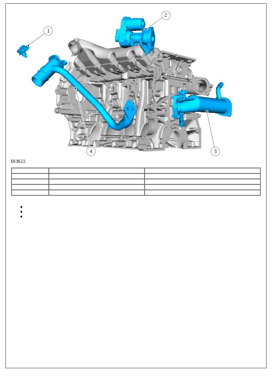
Item
Part Number
Description
1
-
MAPT Sensor
2
-
EGR unit
3
-
EGR cooler
4
-
Connecting pipe
The EGR system comprises:
EGR modulator x 2
EGR cooler x 2
Associated connecting pipes
The EGR modulator and cooler are a combined unit.
The combined EGR modulator and cooler is located under each cylinder bank, between the exhaust manifold and the
cylinder head. The cooler side of the EGR is connected to the vehicle cooling system, via hoses. The inlet exhaust side is
connected directly into the exhaust manifolds on each side. The exhaust gas passes through the cooler and is expelled
via the actuator and a metal pipe into the throttle housing. The EGR modulator is a solenoid operated valve which is
controlled by the ECM. The ECM uses the EGR modulator to control the amount of exhaust gas being re-circulated in
order to reduce exhaust emissions and combustion noise. The EGR is enabled when the engine is at normal operating
temperature and under cruising conditions.
The EGR modulator receives a 12V supply from the ECM and is controlled using a PWM signal. The PWM duty signal of
the solenoid ground is varied to determine the precise amount of exhaust gas delivered to the cylinders.
The modulators are operated through their full range at each engine shut down, to clear any carbon deposits that may
have built up whilst the engine was running
In the event of a failure of the EGR modulator, the EGR function will become inoperative. The ECM can monitor the EGR
modulator solenoid for short circuits and store fault codes in the event of failure. The modulator can also be activated
for testing using the Land Rover recommended diagnostic tool.
FUEL VOLUME CONTROL VALVE
The fuel rail volume control valve is incorporated into the high pressure fuel pump. The VCV spills unwanted fuel back to
the tank (or LP system) or forwards it to the PCV. This avoids unused fuel being pressurized by the HP stage of the
pump, only to be spilt back to LP by the PCV wasting energy and heating the fuel.
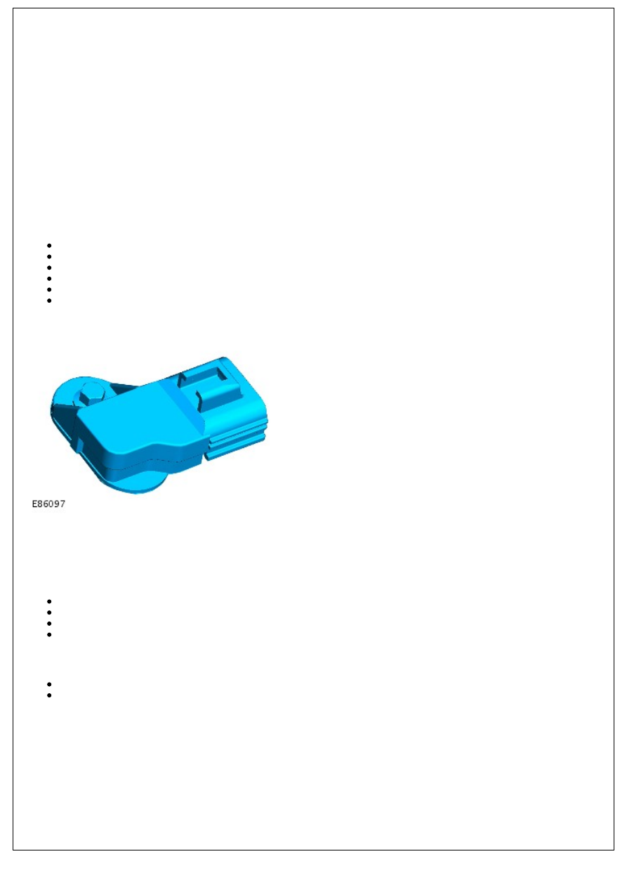
BRAKE LAMP SWITCHES
The brake switch is located on the pedal box and is operated by the brake pedal. The switch is a Hall effect switch which
detects the position of the brake pedal and determines when the driver has applied the brakes. The switch is connected
directly to the ECM.
The brake switch consists of an inner sensor in an outer mounting sleeve. To ensure correct orientation, the sensor is
keyed to the mounting sleeve and the mounting sleeve is keyed to the pedal mounting bracket. Mating serrations hold
the sensor in position in the mounting sleeve. While the brakes are off, the tang on the brake pedal rests against the
end of the sensor. When the brake pedal is pressed, the tang moves away from the sensor and induces a change of
sensor output voltages. This is sensed by the ECM which detects that the brake pedal has been applied. The ECM uses
the brake signal for the following:
To limit fueling during braking
To inhibit/cancel speed control if the brakes are applied.
In the event of a brake switch failure, the following symptoms may be observed:
Speed control inactive
Increased fuel consumption.
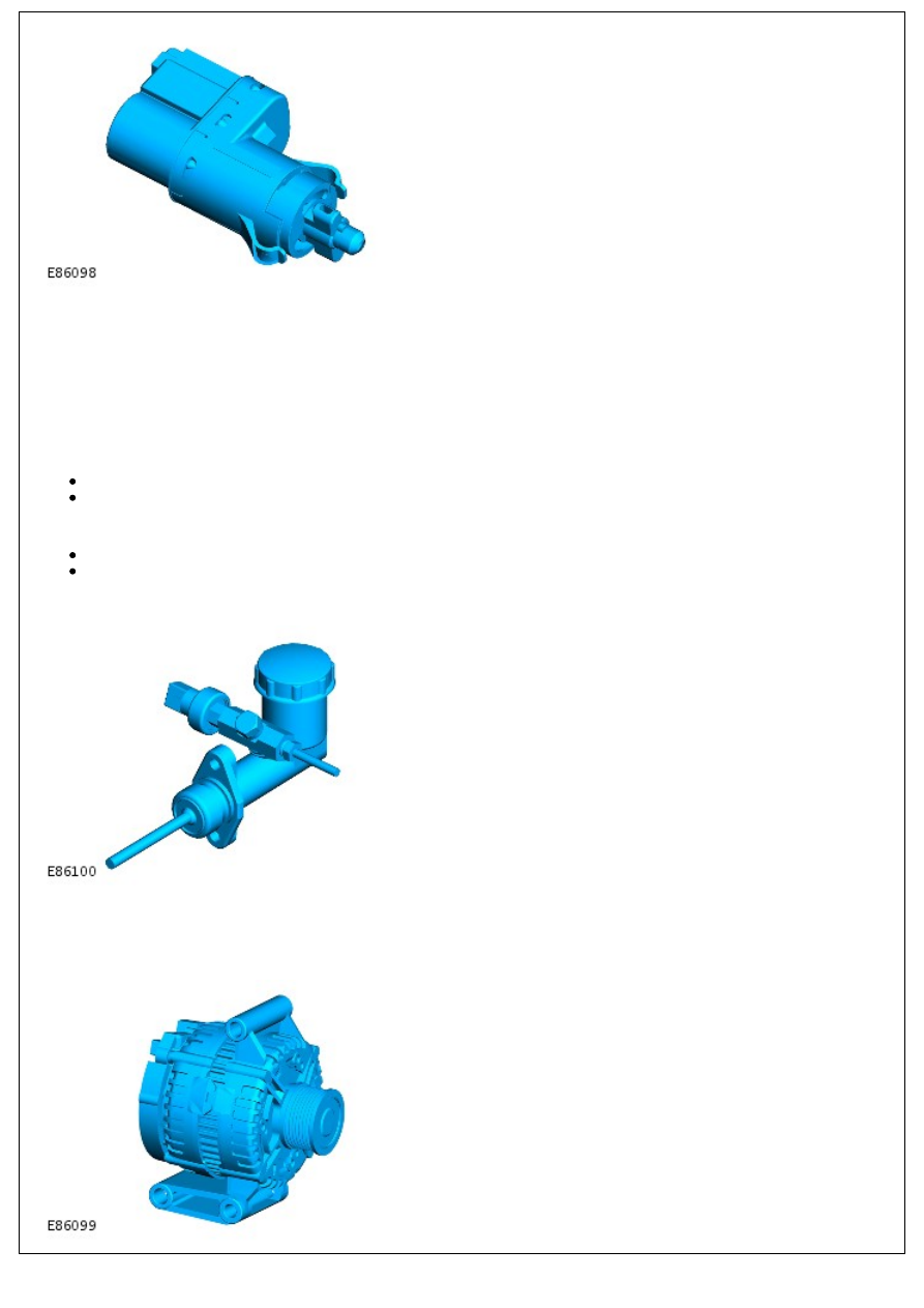
CLUTCH SWITCH
The clutch switch is located on the clutch master cylinder. The clutch switch is a pressure transducer type. When the
clutch is depressed the clutch switch sends a signal to the ECM which reduces engine torque.
GENERATOR
Нет комментариевНе стесняйтесь поделиться с нами вашим ценным мнением.
Текст