Defender 300Tdi (1996+). Manual — part 54
STEERING
3
DESCRIPTION AND OPERATION
Rotary valve operation
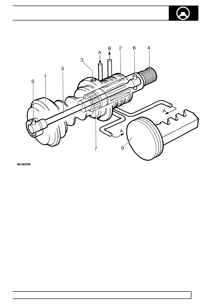
Rotary valve at neutral
The rotary valve assembly comprises a worm (1),
valve sleeve (2), input shaft (4) and torsion bar (5).
The valve sleeve is retained inside the worm by a trim
screw (3), and incorporates valve ports in its inner
bore. The input shaft is attached to the steering wheel
via a steering shaft and steering column and
incorporates valve ports in its outer diameter to align
with those in the sleeve.
The torsion bar, which is secured to the worm and
input shaft with pins (6) at each end, holds the valve
ports in neutral alignment when there is no demand
for assistance.
No demand for assistance (Valve at neutral)
When there is no demand for assistance the torsion
bar holds the input shaft and sleeve valve ports in
neutral relationship to one another, allowing equal
pump pressure (A) to both sides of the piston/rack (9).
Any excess fluid flow from the pump returns to the
reservoir via (B).
57
STEERING
4
DESCRIPTION AND OPERATION
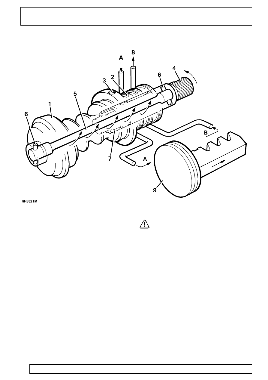
Rotary valve misaligned
Demand for assistance (Valve misaligned)
When the steering wheel and input shaft is turned,
steering resistance transmitted to the worm causes
the torsion bar to be twisted and the valve ports to be
misaligned for a right or left turn. The misalignment of
the valve ports directs all fluid pressure A to one side
of the piston only and allows displaced fluid B on the
other side.
When demanding maximum assistance, any
excessive fluid output from the pump due to high
pump speed, will circulate through the regulator valve
located in the pump unit, causing the temperature of
the fluid and the pump to rise rapidly.
CAUTION: To avoid excessive fluid
temperatures which could damage the oil
seals, the steering must not be held on full
lock for more than 30 seconds in one minute.
Only when the steering wheel, and the demand for
assistance, is released, will the torsion bar return the
valve to neutral, allowing the fluid to circulate through
the reservoir where it is cooled.
In the unlikely event of mechanical failure of the
torsion bar, a coarse splined connection (7) between
the input shaft and worm, ensures steering control is
maintained sufficient to allow the vehicle to be
recovered.
STEERING
5
DESCRIPTION AND OPERATION
Pump and regulator valve operation
The pump which is belt driven from the engine is an
eccentric roller type and also houses the pressure
regulator and flow control valve. The pressure is
controlled by a spring loaded ball valve (3) which is
housed inside the flow control valve piston (4).
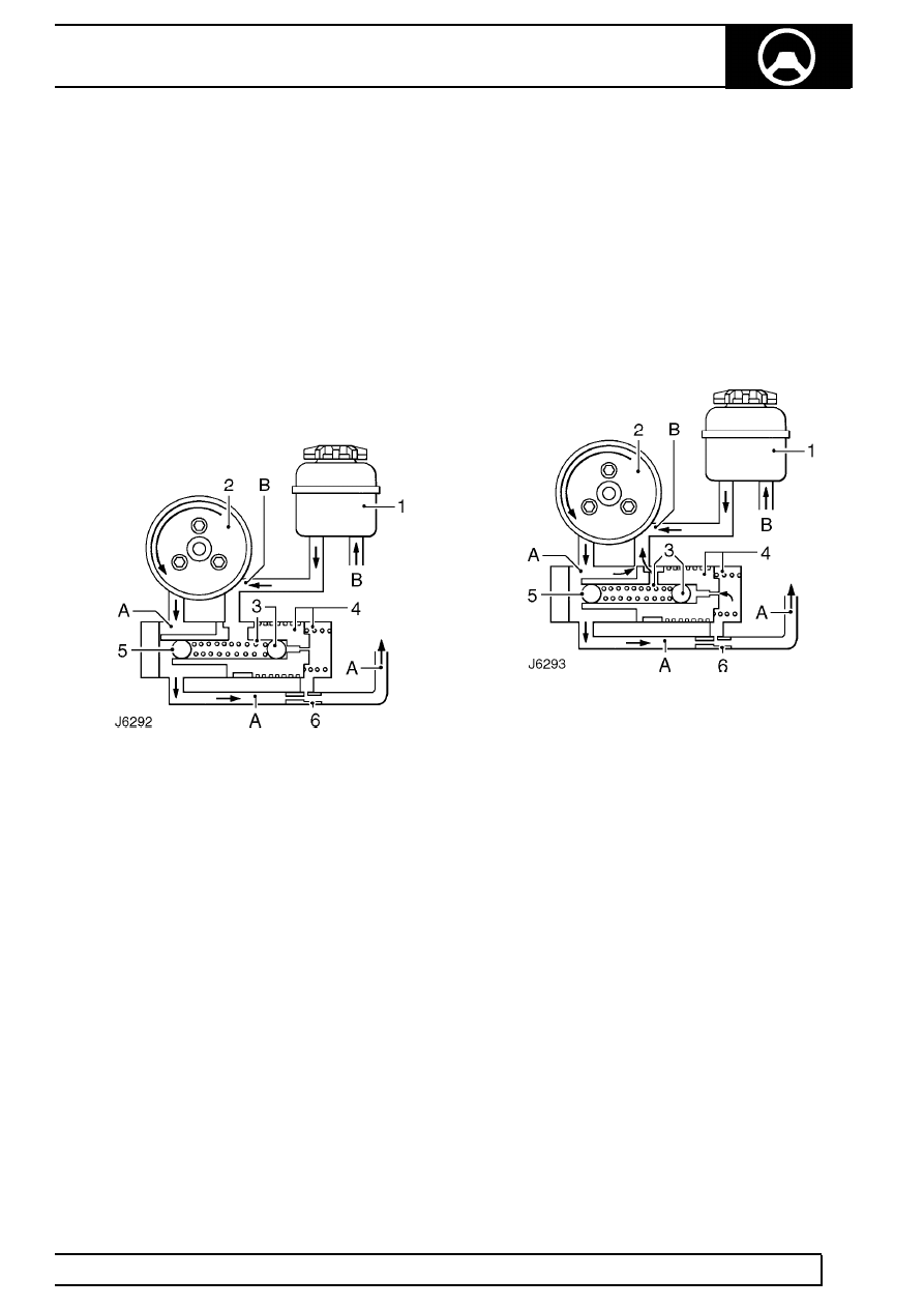
No demand for assistance High flow through box -
Low pressure
With no demand for assistance the rotary valve in the
steering box acts as a pressure relief valve, allowing
fluid (A) to flow freely through the steering box and
back to the reservoir and pump inlet (B).
No demand for assistance
1. Reservoir
2. Pump
3. Pressure control ball valve and spring
4. Flow control valve and spring
5. Press fit plug (ball bearing)
6. Restrictor
The ball plug (5) is pressed into the valve (4)
during manufacture and determines the opening
pressure of pressure relief valve (3).
No flow, through box - High pressure
When the steering is turned, the rotary valve
effectively stops all fluid flow through the steering box,
thus causing an increase in pressure (A). This
increase in pressure is felt in the flow control valve
spring chamber where, at a pre-determined pressure
the relief valve (3) will open and allow the pressure to
escape. The fall in pressure in the flow control spring
chamber, allows the flow control valve to move to the
right, which in turn allows pump output (A) to escape
directly into the pump inlet (B).
Assistance demanded
As soon as the steering wheel is released after
making a turn, the system reverts to the condition
seen in J6292 and the road wheels are returned to the
straight ahead position by the mechanical steering
geometry.
In the event of any hydraulic failure, steering control,
though heavy, will be maintained through the
mechanical components in the steering box.
STEERING
1
FAULT DIAGNOSIS
INSUFFICIENT POWER ASSISTANCE
1. Is fluid level correct?
YES - go to 3.
NO - Fill/bleed sytem
2. Is problem a leak?
YES - Diagnose
See Power Steering Fluid
Leaks .
NO - continue
3. Is drive belt tension correct?
YES - go to 5.
NO - Is drive belt worn or contaminated with oil?
See ELECTRICAL, Repair, Auxiliary drive
belt .
4. Is problem resolved?
YES - end
NO - continue
5. Carry out pressure test at idle and 1000 rev/min.
See Power Steering System - Test .
6. Is correct pressure achieved?
YES - steering box defective
Not at any speed go to 9.
Not at idle go to 7.
7. Is idle speed correct?
YES - Go to 8.
NO - Correct idle speed -
See ENGINE TUNING
DATA, Information, 300 Tdi Engine .
8. Is problem resolved?
YES - end
NO - go to 9.
9. Bypass steering box using adaptor tap
LRT-57-001
10. Is correct pressure obtained?
YES - defective steering box
NO - defective steering pump
CAUTION: Do not hold steering wheel on
full lock for more than 30 seconds in any
one minute to avoid overheating fluid and
possibly damaging seals.
NOTE: 1. Excessive pressure in the
system is almost always caused by a
faulty relief valve in the PAS pump.
NOTE: 2. Insufficient pressure in the
system is usually caused by low fluid level
or PAS pump drive belt slip, or one of the
following: PAS system leaks, faulty PAS pump
relief valve, fault in steering box valve and worm
assembly, leak at piston in steering box, worn
components in PAS pump or box.
Нет комментариевНе стесняйтесь поделиться с нами вашим ценным мнением.
Текст