Defender 300Tdi (1996+). Manual — part 66
FRONT SUSPENSION
5
REPAIR
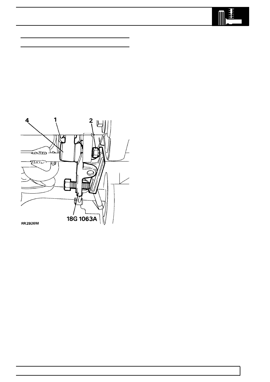
ANTI-ROLL BAR LINKS
Service repair no - 60.10.04.
Remove
1. Remove 2 nuts, bolts, washers and rubber
bushes from ball joint links.
2. Remove cotter pin and loosen castellated nut a
few turns.
3. Release link joint using special tool 18G 1063A
as shown.
4. Remove castellated nut and link.
Refit
5. Fit link and castellated nut. Ensure ball joint link
arm points up. Tighten nut to
40 Nm (30 lbf/ft)
and fit new cotter pin.
6. Align anti-roll bar to links.
7. Fit bolts, washers and rubber bushes using new
self locking nuts and secure anti-roll bar to links.
Tighten fixings to
68 Nm (50 lbf/ft).
FRONT SUSPENSION
1
SPECIFICATIONS, TORQUE
TORQUE VALUES
NOTE: Torque wrenches should be regularly checked for accuracy to ensure that all fixings are
tightened to the correct torque.
Nm
Anti-roll bar
- Strap nyloc nuts
30
. . . . . . . . . . . . . . . . . . . ..
- Ball link self lock nut
68
. . . . . . . . . . . . . . . . . .
- Castellated nut
40
. . . . . . . . . . . . . . . . . . . .
Drag link to axle
40
. . . . . . . . . . . . . . . . . . . . . . .
Securing ring for mounting turret
14
. . . . . . . . . . . . . . . ...
Radius arm to chassis
176
. . . . . . . . . . . . . . . . . . . ...
Panhard rod mounting arm to chassis
88
. . . . . . . . . . . . . ...
Panhard rod to axle
88
. . . . . . . . . . . . . . . . . . . . .
Panhard rod to mounting bracket
88
. . . . . . . . . . . . . . . ...
Tie bar to Panhard rod
110
. . . . . . . . . . . . . . . . . . . ..
Radius arm to axle
197
. . . . . . . . . . . . . . . . . . . . .
REAR SUSPENSION
1
DESCRIPTION AND OPERATION
DESCRIPTION
The rear suspension design locates the rear axle with
two round section steel lower link arms and a forged
’A’ frame, upper link assembly. This system allows
maximum axle articulation and wheel travel while
maintaining roll stiffness and directional stability.
The link arm is secured by a single retaining nut to the
chassis mounting, comprising a rubber bushed
bracket, which is retained by three fixings. A ferrule
rubber bush with a single retaining bolt is used to
secure the link arm to its axle mounting.
The upper link assembly is located on the rear
differential housing by a pivot ball-pin assembly. Two
brackets bolted to the chassis crossmember support
both sides of the ’A’ frame of the link assembly,
secured by single retaining bolts.
A Boge Hydromat self levelling unit can be fitted, as
an option, on 110/130 models to give additional
support when the vehicle is used to carry heavier
loads.
Two rubber bearing bushes, with retaining straps,
secure the rear of the anti-roll bar, if fitted, to the
chassis mountings, while bushed links support the
front of the anti-roll bar to the axle.
Conventional long travel coil springs and hydraulic
shock absorbers are used to control body movement.
The shock absorbers are secured to chassis mounting
brackets and fabricated lower mountings welded to to
the rear axle. Retaining plates are used to secure the
coil springs to the axle mounting while fabricated
brackets, welded to the chassis, are used for the
upper spring location.
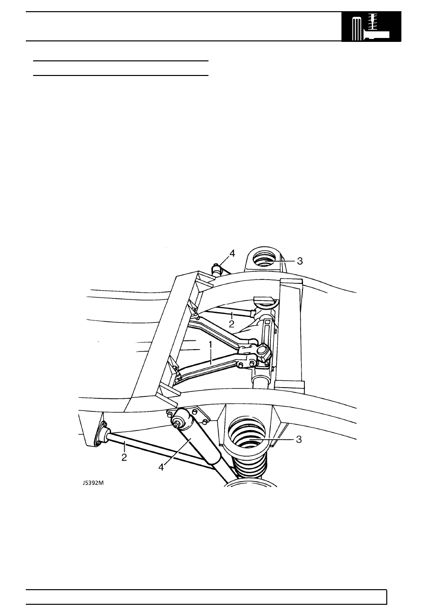
Rear axle suspension
1. ’A’ frame, upper link assembly
2. Lower link
3. Coil springs
4. Shock absorber
REAR SUSPENSION
1
REPAIR
REV: 09/97
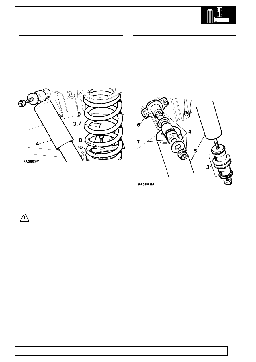
REAR ROAD SPRING
Service repair no - 64.20.01.
Remove
1. Loosen rear road wheel retaining nuts.
2. Support chassis on stands and remove wheels.
3. Support rear axle weight with jack.
4. Disconnect shock absorbers at one end.
5. Position coil spring compressor correctly on road
spring.
6. Compress spring evenly to facilitate removal.
7. Lower axle to free road spring from upper seat.
CAUTION: Avoid lowering axle further than
rear brake flexible hose will allow.
8. Remove spring retainer plate.
9. Withdraw road spring.
10. Collect spring seat.
Refit
11. Position spring seat on axle location.
12. Fit road spring into chassis location and, using a
turning motion, fit to spring seat.
13. Fit spring retainer plate. Tighten bolts to
14 Nm
(10 lbf/ft).
14. Secure shock absorber. Tighten fixing to
37 Nm
(27 lbf/ft).
15. Fit road wheels, remove chassis stands and
jack. Tighten wheel nuts to correct torque:
Alloy wheels -
130 Nm (96 lbf/ft)
Steel wheels -
100 Nm (80 lbf/ft)
Heavy duty wheels -
170 Nm (125 lbf/ft)
REAR SHOCK ABSORBER
Service repair no - 64.30.02.
Remove
1. Loosen road wheel retaining nuts.
2. Support chassis on stands. Remove road wheel
and support rear axle weight with jack.
3. Remove fixings and withdraw shock absorber
from axle bracket.
4. Remove upper fixings.
5. Withdraw shock absorber.
6. If required, remove mounting bracket
7. If required, remove mounting rubbers.
Refit
8. Position shock absorber and fit upper fixings.
9. Secure shock absorber with lower fixings to axle
bracket. Tighten upper and lower fixings to
37
Nm (27 lbf/ft).
10. Fit road wheels, remove chassis stands and
jack. Tighten wheel nuts to correct torque:
Alloy wheels -
130 Nm (96 lbf/ft)
Steel wheels -
100 Nm (80 lbf/ft)
Heavy duty wheels -
170 Nm (125 lbf/ft)
Нет комментариевНе стесняйтесь поделиться с нами вашим ценным мнением.
Текст