Defender 300Tdi (1996+). Manual — part 101
WIPERS AND WASHERS
9
REPAIR
13. Fit wheelboxes to bulkhead.
14. Fit drive tubes to wheelboxes.
15. Feed drive rack through tubes until fully seated
in both wheelboxes.
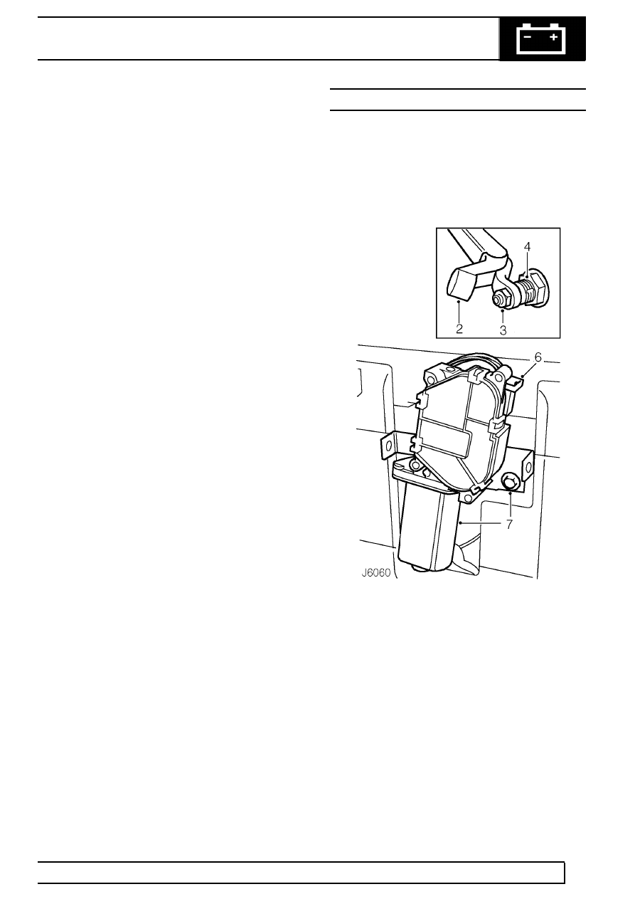
16. Secure drive tube nut to wiper motor.
17. Fit wiper motor strap and earth lead.
18. When all components are correctly aligned, fully
tighten wheelboxes nuts to secure drive tubes.
Tighten wheelbox to bulkhead nuts.
19. Fully tighten drive tube nut to wiper motor and
motor strap screws.
20. Connect multiplug to wiper motor and earth lead
to strap tag.
21. Fit spacer, where used, early vehicles only.
22. Fit wiper arm adaptors.
23. Reconnect battery and check operation of wiper
motor and drive assembly and wheelboxes.
24. Disconnect battery.
25. Fit steering column upper and lower supports.
Tighten fixings to correct torque.
26. Fit demister vent top duct.
27. Secure RH demister vent and hose.
28. Fit LH and RH demister vents to ducts.
29. Fit centre and LH fascia top crash rail support
brackets.
30. Fit all other components removed to gain access
to wiper motor and wheelboxes.
31. Reconnect battery, check wiper motor operation
again and adjust wiper arms, if necessary.
REAR WIPER MOTOR
Service repair no - 84.35.12
Remove
1. With assistance, unscrew 3 retaining nuts and
remove spare wheel from rear door mounting
studs.
2. Lift wiper arm end cap to gain access to securing
nut.
3. Remove nut and withdraw wiper arm from drive
spindle.
4. Remove retaining nut, plain washer and rubber
washer securing wiper motor drive spindle to
door.
5. Remove 2 screws and remove cover from wiper
motor mounting bracket.
6. Disconnect wiper motor harness multi-plug.
7. Remove bolt, with rubber washer, and detach
wiper motor, complete with mounting bracket,
from rear door.
84
WIPERS AND WASHERS
10
REPAIR
Refit
8. Locate wiper motor drive spindle through
aperture in rear door.
9. Position wiper motor mounting bracket and
secure to rear door. Tighten bolt to
23 Nm (17
lbf/ft).
10. Reconnect harness multi-plug.
11. Secure drive spindle to door.
12. Fit wiper motor cover.
13. Fit rear wiper arm.
14. Fit spare wheel. Tighten retaining nuts to
130Nm
(96 lbf/ft).
WIPERS AND WASHERS
1
OVERHAUL
WIPER MOTOR
Service repair no - 84.15.18.
Dismantle
1. Remove wiper motor from vehicle
See Repair,
Wiper motor and drive rack.
2. Remove wiper motor gearbox cover.
3. Remove circlip and plain washer securing
connecting rod.
4. Withdraw connecting rod.
5. Withdraw flat washer.
6. Remove circlip and washer securing shaft and
gear.
7. Clean any burrs from gear shaft and withdraw
gear.
8. Withdraw dished washer.
9. Add alignment marks to yoke and gearbox for
reassembly.
10. Remove yoke securing bolts.
11. Withdraw yoke and armature.
12. Remove brush gear assembly.
13. Remove limit switch.
Inspection and test
14. Check brushes for excessive wear, if they are
worn to 4,8 mm in length, fit a new brush gear
assembly.
15. Using a push type gauge, check that brush
spring pressure is 140 to 200 g when bottom of
brush is level with bottom of slot in brush box. Fit
a new brush gear assembly if springs are not
satisfactory.
16. Test armature for insulation and open- or
short-circuits. Use a 110 V 15 W test lamp. Fit a
new armature if faulty.
17. Examine gear wheel for damage or excessive
wear.
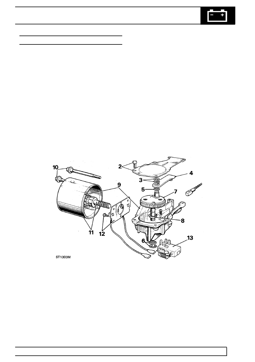
Key to wiper motor components
1. Flexible drive
2. Gearbox cover
3. Connecting-rod retaining washer and circlip
4. Connecting-rod
5. Flat washer
6. Gear shaft retaining washer and circlip
7. Drive gear
8. Dished washer
9. Alignment marks - yoke to body
10. Yoke securing bolts
11. Armature and yoke
12. Brush gear assembly
13. Limit switch

84
WIPERS AND WASHERS
2
OVERHAUL
Assemble
Use Ragosine Listate Grease to lubricate gear wheel
teeth, armature shaft worm gear, connecting rod and
pin, cable rack and wheelbox gear wheels.
Use Shell Turbo 41 oil sparingly to lubricate bearing
bushes, armature shaft bearing journals, gear wheel
shaft and wheelbox spindles. Thoroughly soak felt
washer in yoke bearing with oil.
18. Fit limit switch.
19. Fit brush gear assembly.
20. Fit armature and yoke to gearbox using
alignment marks, secure with yoke retaining
bolts tightening to
23 Nm (17 lbf/ft). If a
replacement armature is being fitted slacken
thrust screw to provide end-float for fitting yoke.
21. Fit dished washer beneath gear wheel with
concave side towards gear wheel.
22. Fit gear wheel to gearbox.
23. Secure gear wheel shaft with plain washer and
circlip.
24. Fit larger flat washer over crankpin.
25. Fit connecting rod and secure with smaller plain
washer and circlip.
26. Fit gearbox cover and secure with retaining
screws.
27. Connect electrical leads between wiper motor
and limit switch.
28. To adjust armature shaft end-float, hold yoke
vertically with adjuster screw uppermost.
Carefully screw in adjuster until resistance is felt,
then back-off one quarter turn.
Нет комментариевНе стесняйтесь поделиться с нами вашим ценным мнением.
Текст