Defender 300Tdi (1996+). Manual — part 70

70
BRAKES
4
REPAIR
PRESSURE REDUCING VALVE (PRV)
Service repair no - 70.25.21
Remove
1. Disconnect battery.
2. Clean area around reducing valve ports.
3. Place a container under valve to catch escaping
brake fluid.
4. Disconnect primary circuit pipe unions æAæ
from valve.
5. Disconnect secondary circuit pipe unions æBæ
from valve.
6. Cover pipes to prevent ingress of dirt.
7. Remove single retaining nut and bolt securing
valve to engine bulkhead.
8. Remove valve.
Refit
9. Fit valve to engine bulkhead. Tighten bolt to
15
Nm (11 lbf/ft).
10. Connect primary and secondary circuit pipes to
valve. Tighten to
16 Nm (12 lbf/ft).
11. Fill brake reservoir with recommended brake
fluid
See LUBRICANTS, FLUIDS AND
CAPACITIES, Information, Recommended
lubricants and fluids .
12. Bleed the brake system
See Brake system
bleed .
13. Reconnect battery and road test vehicle.
SERVO NON RETURN VALVE
Service repair no - 70.50.15
Remove
1. Disconnect brake vacuum hose from servo non
return valve.
2. Carefully prise valve out with a screwdriver blade
between valve and grommet. Take care not to
exert too much pressure on the vacuum
chamber.
3. Remove rubber grommet but be careful not to
allow it to fall into the vacuum chamber.
4. Check the valve for correct operation; it should
not be possible to pass air through into the servo
in direction of arrow. Do not use compressed air.
Refit
5. Fit rubber grommet.
6. Smear ribs of the valve with Lucas Girling rubber
grease to assist assembly, and push valve fully
home.
7. Connect vacuum hose to the valve.
8. Road test vehicle.

BRAKES
5
REPAIR
SERVO ASSEMBLY
Service repair no - 70.50.01
Remove
Before starting repair refer to general brake service
practice
See General Brake Service Practice .
NOTE: The non-return valve and grommet,
are the only serviceable components. In
event of failure or damage, fit a new unit.
1. Remove master cylinder
See Master cylinder .
2. Disconnect vacuum supply hose from servo unit.
3. At footwell, release 2 brake pedal return springs.
4. Disconnect leads from brake light switch at rear
of pedal box.
5. Remove blanking grommets from each side of
pedal box.
6. Remove split pin and clevis pin securing servo
push rod to brake pedal.
7. Remove 4 nuts and plain washers securing
servo to pedal box.
8. Remove servo assembly and rubber washer
from bulkhead.
Refit
9. Locate servo assembly and rubber washer to
engine bulkhead and secure to pedal box.
Tighten fixings to
14 Nm (10 lbf/ft).
10. Fit brake pedal to servo push rod with clevis pin
and new split pin.
11. Fit blanking grommets to each side of pedal box.
12. At footwell, attach pedal return springs.
13. Connect vacuum hose to servo non-return valve.
14. Fit brake master cylinder to servo unit
See
Master cylinder .

70
BRAKES
6
REPAIR
BRAKE PEDAL
Service repair no - 70.35.01 - Brake pedal
Service repair no - 70.35.03 - Pedal box
Remove
1. Remove brake servo assembly.
See Servo
assembly .
2. Remove 6 bolts securing pedal box to engine
bulkhead.
3. Taking care not damage brake fluid pipes,
remove pedal box assembly and gasket.
4. Release return springs from pedal and pedal box
bosses.
5. Using a suitable punch, drift out retaining pin and
withdraw pedal pivot shaft.
6. Remove brake pedal complete with pivot
bushes.
7. Examine components for wear or damage,
renew as necessary.
8. If it is necessary to fit new pivot bushes, they
must be reamed out to 15,87 mm
±
0,02 mm
(0.625
±
0.001 in) after fitment.
Refit
9. Lubricate pedal pivot shaft and bushes with
general purpose grease.
10. Fit pedal to pedal box, insert pivot shaft and
secure with new split pin.
11. Attach return springs to pedal and pedal box
bosses.
12. Fit pedal box and gasket to engine bulkhead.
Tighten fixings to
25 Nm (18 lbf/ft).
13. Fit brake servo assembly.
See Servo
assembly .
BRAKES
7
REPAIR
REV: 09/97
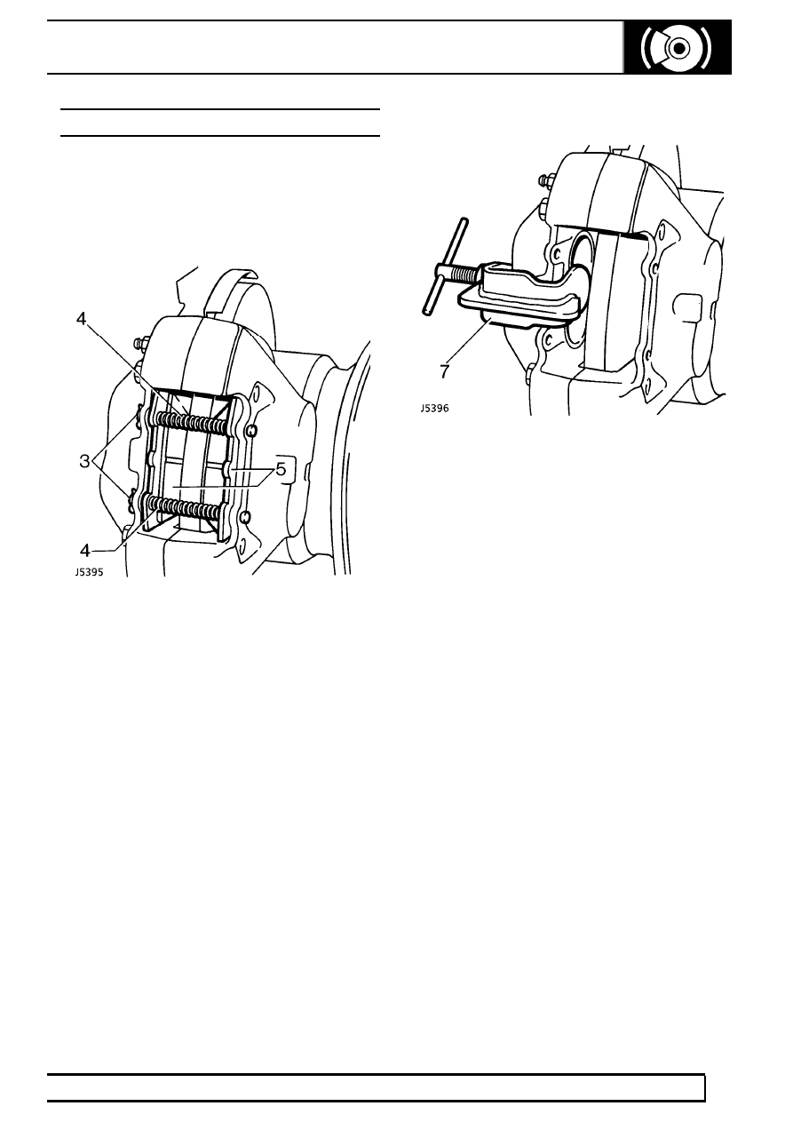
FRONT BRAKE PADS - ALL MODELS
Service repair no - 70.40.02
Remove
1. Remove front road wheels .
2. Clean exterior of calipers.
3. Remove split pin from retaining pins.
4. Remove pad retaining pins and anti-rattle
springs.
5. Remove brake pads.
6. Clean exposed parts of pistons, using new brake
fluid. Wipe away excess with a lint free cloth.
7. Using piston clamp LRT-70-500 press each
piston back into its bore. Ensure that displaced
brake fluid does not overflow from reservoir.
Refit
8. Fit brake pads.
9. Fit pad retaining pins and anti-rattle springs.
Secure with new split pins.
10. Apply service brake pedal several times to locate
pads.
11. Fit road wheels. Tighten wheel nuts to correct
torque:
Alloy wheels -
130 Nm (96 lbf/ft)
Steel wheels -
100 Nm (80 lbf/ft)
Heavy duty wheels -
170 Nm (125 lbf/ft)
12. Check fluid reservoir. Top up if necessary, using
correct grade of fluid
See LUBRICANTS,
FLUIDS AND CAPACITIES, Information,
Recommended lubricants and fluids .
Нет комментариевНе стесняйтесь поделиться с нами вашим ценным мнением.
Текст