Defender 300Tdi (1996+). Manual — part 51
FRONT AXLE AND FINAL DRIVE
1
FAULT DIAGNOSIS
FAULT DIAGNOSIS
Complaint - Oil leaks
An external leak of lubrication can be caused by a
faulty internal seal. For example, if the seals which
separate the differential from the swivel housings are
faulty and the vehicle is operating or parked on an
embankment, oil may leak across the axle leaving one
swivel with a high level and the opposite swivel and
differential lacking lubrication.
See ’Description and Operation’ for illustrations of oil
seal locations.
When investigating leaks or checking oil levels, it is
essential that all the lubrication is drained from any
housing with a high level and that the other levels are
checked.
Swivel oil should be checked for signs of grease
leaking from the hub bearings and oil contamination of
the hub grease.
Check that the axle ventilation system is clear, as a
blockage can cause internal pressure to force oil past
the seals.
If the vehicle is driven in deep water with defective oil
seals, water may contaminate the lubricants and when
checked, give a false impression that the housing has
been overfilled with oil.
Do not assume that a high oil level is due to over
filling or, that a low level is because of an external
leak.
FRONT AXLE AND FINAL DRIVE
1
REPAIR
REV: 09/97
FRONT AXLE ASSEMBLY
Service repair no - 54.10.01
Remove
WARNING: Remove and refit of axle
requires a further two persons to steady
axle when lowering or repositioning axle.
1. Support chassis front.
2. Remove road wheels.
3. Support axle weight with hydraulic jack.
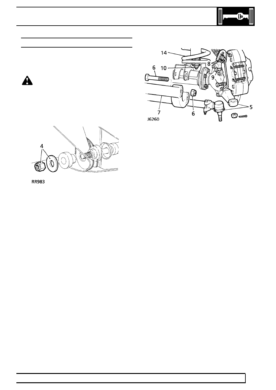
4. Remove radius arms to chassis frame nuts.
5. Disconnect steering damper from track rod.
Using a extractor remove track rod links from
swivel pin arms.
6. Remove four nuts and bolts securing radius
arms to axle bracket.
7. Remove radius arms.
8. Remove bolts securing brake hose brackets .
Refit bolts to prevent oil leakage.
9. Remove bolts from brake calipers and tie to one
side.
10. Remove nuts and washers securing shock
absorbers to axle.
11. Disconnect drag link from swivel pin housing
arm.
12. Remove two nuts and bolts securing panhard
rod to axle bracket. Lift rod clear of axle.
13. Mark for reassembly drive shaft flanges.
Remove four nuts and bolts, tie propeller shaft to
one side.
14. Release axle ventilation pipe banjo and lower
axle assembly. Remove road springs.
15. Disconnect anti-roll bar link
See FRONT
SUSPENSION, Repair, Anti-roll bar ball .
16. Remove axle assembly.
Refit
17. Position axle under vehicle, supporting left side
of axle, and fit anti-roll bar links
See FRONT
SUSPENSION, Repair, Anti-roll bar links .
18. Fit propeller shaft. Tighten bolts to
47 Nm (35
lbf/ft).
19. Fit panhard rod to axle bracket. Tighten bolts to
88 Nm (65 lbf/ft).
20. Fit drag link to swivel pin arm. Tighten fixings to
40 Nm (30 lbf/ft).
21. Fit shock absorbers to axle.
22. Fit brake calipers. Tighten bolts to
82 Nm (60
lbf/ft).
23. Tighten upper swivel pin bolts to
78 Nm (58
lbf/ft).
24. Fit radius arms to axle brackets. Tighten bolts to
197 Nm (145 lbf/ft).
25. Fit steering damper to track rod.
26. Fit radius arms to chassis side member. Tighten
fixings to
197 Nm (145 lbf/ft).
27. Tighten track rod end to
40 Nm (30 lbf/ft) and fit
new split pin.
28. Remove chassis supports, fit road wheels and
tighten to correct torque:
Alloy wheels -
130 Nm (96 lbf/ft)
Steel wheels -
100 Nm (80 lbf/ft)
Heavy duty wheels -
170 Nm (125 lbf/ft)
54
FRONT AXLE AND FINAL DRIVE
2
REPAIR
FRONT HUB ASSEMBLY
Service repair no - 60.25.01.
Remove
1. Loosen front wheel nuts, jack up vehicle and
lower onto axle stands and remove road wheel.
2. Release brake hose clips and remove brake
caliper and brake disc shield bolts. Secure to
one side.
3. Lever off dust cap.
4. Remove circlip and drive shaft shim from
driveshaft.
5. Remove 5 bolts and withdraw driving member
and joint washer.
6. Bend back lock washer tabs.
7. Remove locknut and lock washer.
8. Remove hub adjusting nut.
9. Remove spacing washer.
10. Remove hub and brake disc assembly complete
with bearings.
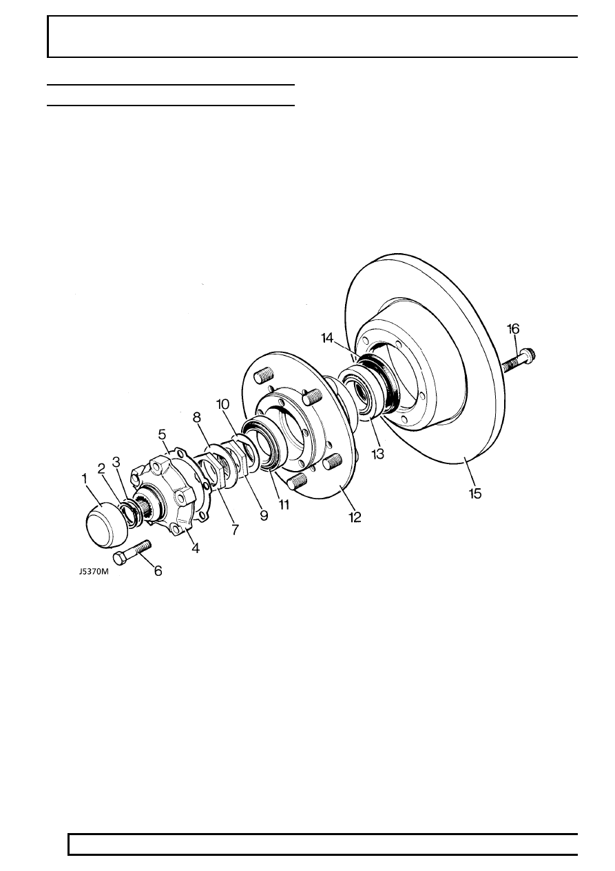
HUB COMPONENTS
1. Dust cap.
2. Drive shaft circlip.
3. Drive shaft shim.
4. Drive member.
5. Drive member joint washer.
6. Drive member retaining bolt.
7. Lock nut.
8. Lock washer.
9. Hub adjusting nut.
10. Spacing washer.
11. Outer bearing.
12. Hub.
13. Inner bearing.
14. Grease seal.
15. Brake disc
16. Disc retaining bolt.
FRONT AXLE AND FINAL DRIVE
3
REPAIR
REV: 09/97
Refit
11. Clean stub axle and drive shaft and fit hub
assembly to axle.
12. Fit spacing washer.
13. Fit hub adjusting nut. Tighten to
50 Nm (37
lbf/ft). Ensure hub is free to rotate with no
bearing play.
14. Back off adjusting nut 90
°
and tighten to
10 Nm
(7 lbf/ft).
15. Fit a new lock washer.
16. Fit locknut. Tighten to
50 Nm (37 lbf/ft).
17. Tab over lock washer to secure adjusting nut
and locknut.
18. Fit a new joint washer to driving member and fit
member to hub. Tighten bolts to
65 Nm (48
lbf/ft).
19. Fit original drive shaft shim and secure with a
circlip.
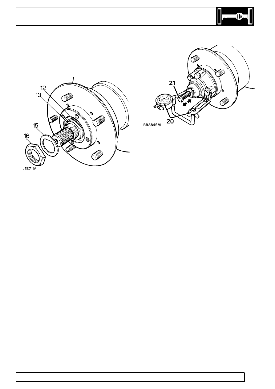
20. To check drive shaft end play, mount a dial
gauge using bracket LRT-99-503 and rest pin in
a loaded condition on end of drive shaft.
21. Fit a suitable bolt to threaded end of drive shaft.
Move drive shaft in and out noting dial gauge
reading. End play should be between 0,08 to
0,25 mm.
22. If end play requires adjustment, remove circlip,
measure shim thickness and fit an appropriate
shim to give required end-play.
23. Remove bolt from drive shaft, fit circlip and dust
cap.
24. Fit brake disc shield and brake caliper. Tighten
fixings to
82 Nm (60 lbf/ft).
25. Bleed brake system
See BRAKES, Repair,
Brake system bleed .
26. Fit road wheel, remove axle stands and tighten
road wheel nuts to correct torque:
Alloy wheels -
130 Nm (96 lbf/ft)
Steel wheels -
100 Nm (80 lbf/ft)
Heavy duty wheels -
170 Nm (125 lbf/ft)
27. Operate footbrake to locate brake pads before
driving vehicle.
Нет комментариевНе стесняйтесь поделиться с нами вашим ценным мнением.
Текст