Frelander 2. Manual — part 457
1
2
1
2
3
4
5
1
Is the battery warning lamp illuminated?
Yes
GO to Pinpoint Test
C.
No
The generator output is within the expected range, Do not replace the generator. If customer
concern is still evident contact dealer technical support
PINPOINT TEST C : BOSCH NON-BMS GENERATOR DIAGNOSTIC FLOW CHART
TEST
CONDITIONS
DETAILS/RESULTS/ACTIONS
C1: CIRCUIT CHECKS
• NOTE: Freelander 2 = Charge warning lamp is driven by the central junction box (from the powertrain control module) to
the instrument panel cluster via the CAN bus
• NOTE: Defender = Charge warning lamp is driven by the powertrain control module to the instrument panel cluster via
the CAN bus
Freelander 2 = Refer to the electrical circuit diagrams and check the (LIN) circuit between the
generator and the engine control module for short circuit to ground, short circuit to power, open
circuit, high resistance faults
Defender = Refer to the electrical circuit diagrams and check the (D+ and ALTMON) circuits between
the generator and the engine control module for short circuit to ground, short circuit to power, open
circuit, high resistance faults
Are any circuit faults evident?
Yes
Repair the circuit as required GO to Pinpoint Test
B.
No
GO to Pinpoint Test
D.
PINPOINT TEST D : BOSCH NON-BMS GENERATOR DIAGNOSTIC FLOW CHART
TEST
CONDITIONS
DETAILS/RESULTS/ACTIONS
D1: CIRCUIT CHECKS 1
• NOTE: Freelander 2 = The heated rear screen is timed to operate for 12 minutes
• NOTE: Defender = The heated rear screen is timed to operate for 8 minutes
Connect a voltmeter to the vehicle battery
Switch ignition state to on (engine off)
Turn off all electrical loads e.g. (blower, radio, interior lights etc.)
Start the engine, switch on the heated rear screen
Ensure the heated rear screen is on (see note above) and that the air conditioning system is off.
Voltage measurement
Measure the voltage drop between the generator body and battery negative terminal and record
the value (V2)
Does the voltage drop value (V2) = less than 0.3 Volts ?
Yes
GO to D2
.
No
Switch off engine. Circuit check. Refer to the electrical circuit diagrams, check the generator body
and battery negative cables for loose or corroded connections. Repair any circuit faults, retest the
generator GO to Pinpoint Test
B.
D2: CIRCUIT CHECKS 2
Voltage measurements
Measure the voltage drop between the generator B+ terminal and battery positive terminal and
record value (V3)
Does the voltage drop value (V3) = less than 0.3 Volts ?
Yes
Install a new generator. Refer to the warranty policy and procedures manual, or determine if any
prior approval programme is in operation, prior to the installation of a new module/component
No
Switch off engine. Circuit check. Refer to the electrical circuit diagrams check the generator B+
terminal and positive battery cables for loose or corroded connections. Repair any circuit faults,
retest the generator GO to Pinpoint Test
B.

Battery, Mounting and Cables -
General Specification
Item
Specification
Battery - All models:
Type
Exide H7
Capacity
80Ah/700CCA
Reserve capacity
125 minutes
Battery Disconnect/Connect
CAUTION: The vehicle status and battery condition must be established before attempting battery
disconnect/connect. Reference must be then made to the following table to establish the relevant procedure to be
followed.
• NOTE: Vehicles fitted with a fuel fired booster heater will require a 5 minute wait before telestart function will operate.
Cycle the ignition off->on->off. W ait 5 minutes to allow fuel fired booster heater to store vehicle configuration
parameters.
Vehicle status
Battery charged
Battery discharged
Procedure
Procedure
Engine running
1
Vehicle powered down, locked and alarmed
2
3
Vehicle unlocked
4
5
Procedure 1
Disconnect battery
Connect battery
1. Apply parking brake or
alternatively, chock wheels
1. Ensure that all electrical loads are switched OFF
2. Switch off ignition and
remove the remote control.
2. Connect battery leads - GROUND lead last
3. Wait 2 minutes for engine
management system to 'power
down'
3. Switch on ignition
4. Open the hood
4. Reset radio station preset buttons.
5. Disconnect battery - GROUND
lead first
5. Reset clock
6. Reset electric window one-touch facility. Power window up to hard stop, release
switch, reapply and hold for 1 second (relay in door will click). Lower window to stop,
reapply and hold for one second. One touch should now work
Procedure 2
Disconnect battery
Connect battery
1. Unlock the vehicle and disarm
the alarm using the remote
control
1. Ensure that all electrical loads are switched OFF
2. Apply parking brake or
alternatively, chock wheels
2. Connect battery leads - GROUND lead last
3. Wait 2 minutes for engine
management system to 'power
down'
3. Switch on ignition
4. Open the hood
4. Reset radio station preset buttons.
5. Disconnect battery - GROUND
lead first
5. Reset clock
6. Reset electric window one-touch facility. Power window up to hard stop, release
switch, reapply and hold for 1 second (relay in door will click). Lower window to stop,
reapply and hold for one second. One touch should now work
• NOTE: 1. Disconnect battery - If the remote control is not functioning, it will be necessary to manually unlock the
vehicle using the key.
Procedure 3
Disconnect battery
Connect battery
1. Unlock the vehicle from the LH front
door using the key
1. Ensure that all electrical loads are switched OFF
2. Enter the vehicle, and dock the
remote control to silence the alarm.
2. Connect battery leads - GROUND lead last
3. Remove the remote control and wait
2 minutes for engine management
system to 'power down'
3. Switch on ignition
4. Open the hood
4. Reset radio station preset buttons.
5. Disconnect battery - GROUND lead
first
5. Reset clock
6. Reset electric window one-touch facility. Power window up to hard stop,
release switch, reapply and hold for 1 second (relay in door will click). Lower
window to stop, reapply and hold for one second. One touch should now work
• NOTE: 1. Connect battery - If there is insufficient capacity in the battery to disarm the alarm, the alarm may sound on
reconnection of the battery - Step 2 will disarm the alarm
Procedure 4
Disconnect battery
Connect battery

1. Apply parking brake or
alternatively, chock wheels
1. Ensure that all electrical loads are switched OFF
2. Open the hood
2. Connect battery leads - GROUND lead last
3. Disconnect battery -
GROUND lead first
3. Switch on ignition
4. Reset radio station preset buttons.
5. Reset clock
6. Reset electric window one-touch facility. Power window up to hard stop, release switch,
reapply and hold for 1 second (relay in door will click). Lower window to stop, reapply and
hold for one second. One touch should now work
Procedure 5
Disconnect battery
Connect battery
1. Apply parking brake or
alternatively, chock wheels
1. Ensure that all electrical loads are switched OFF
2. Open the hood
2. Connect battery leads - GROUND lead last
3. Disconnect battery -
GROUND lead first
3. Switch on ignition
4. Reset radio station preset buttons.
5. Reset clock
6. Reset electric window one-touch facility. Power window up to hard stop, release switch,
reapply and hold for 1 second (relay in door will click). Lower window to stop, reapply and
hold for one second. One touch should now work
Torque Specifications
Description
Nm
lb-ft
Battery tray to support bracket
10
7
Battery terminal nuts
10
7
Battery support bracket to body:
M8 nut
24
18
M8 bolt
24
18
Battery, Mounting and Cables - Battery and Cables
Description and Operation
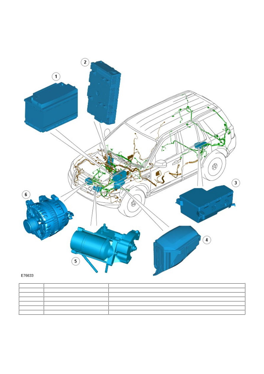
COMPONENT LOCATION
• NOTE: TD4 shown, i6 similar
Item
Part Number
Description
1
-
Battery
2
-
Central Junction Box (CJB)
3
-
Auxiliary Junction Box (AJB)
4
-
Battery Junction Box (BJB)
5
-
Starter motor
6
-
Generator
OVERVIEW
The battery is located behind a cover on the Left Hand (LH) side of the engine compartment. The battery sits in a tray and
is secured in position with a clamp plate and bolt assembly. The battery supplies electrical power to the starter motor,
generator and BJB.
The BJB is mounted adjacent the LH front suspension turret. The BJB contains fusible links, blade and J-case fuses, and
relays to distribute electrical power to various vehicle systems and junction boxes.
Нет комментариевНе стесняйтесь поделиться с нами вашим ценным мнением.
Текст