Frelander 2. Manual — part 321
Item
Part Number
Description
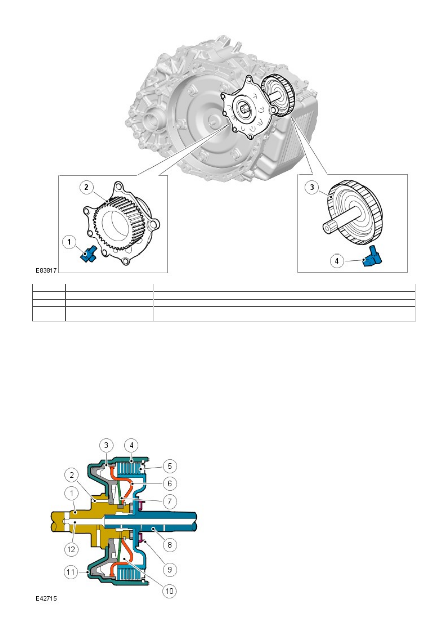
1
-
Speed Sensor (SP) - Output shaft speed
2
-
Counter drive gear
3
-
C2 clutch drum
4
-
Speed sensor (NIN)
Two speed sensors (NIN and SP) are used in the transmission and are located within the transmission housing. Speed
sensor (SP) is located adjacent to the counter drive gear and reads from the gear teeth to provide an output shaft speed
signal. Speed sensor (NIN) is located adjacent to the clutch C" drum and reads off teeth on the outer circumference of the
drum to provide an input shaft speed. Both speed signals are received by the TCM which uses the 2 signals to calculate
engine torque output, shift timing and torque converter lock-up.
Fluid Temperature Sensor
The fluid temperature sensor is integrated into the internal wiring harness within the transmission. It detects the fluid
temperature in the hydraulic pressure control circuit and transmits a signal corresponding to the temperature to the TCM.
The TCM monitors the temperature and provides smooth gear shifts across a wide range of temperatures.
DRIVE CLUTCHES
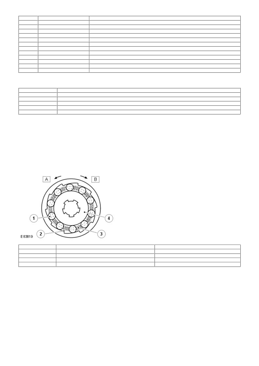
Multiplate Drive or Brake Clutch – Typical
Item
Part Number
Description
1
-
Input shaft
2
-
Main pressure supply port
3
-
Piston
4
-
Cylinder – External plate carrier
5
-
Clutch plate assembly
6
-
Baffle plate
7
-
Diaphragm spring
8
-
Output shaft
9
-
Bearing
10
-
Dynamic pressure equalisation chamber
11
-
Piston chamber
12
-
Lubrication channel
There are three drive clutches and two brake clutches (B2 is a multiplate brake clutch & B1 is a double wrap brake band)
used in the AW F21 transmission. Each clutch comprises one or more friction plates dependent on the output controlled. A
typical clutch consists of a number of steel outer plates and inner plates with friction material bonded to each face.
Clutch / Brake
Operation
C1 Clutch
Connects the front planetary carrier to the rear planetary rear sun gear
C2 Clutch
Connects the intermediate shaft to the rear planetary carrier
C3 Clutch
Connects the front planetary carrier to the rear planetary middle sun gear
B1 Brake
Locks the rear planetary middle sun gear
B2 Brake
Locks the rear planetary carrier
The clutch plates are held apart mechanically by a diaphragm spring and hydraulically by dynamic pressure. The pressure is
derived from a lubrication channel which supplies fluid to the bearings etc. The fluid is passed via a drilling in the output
shaft into the chamber between the baffle plate and the piston. To prevent inadvertent clutch application due to pressure
build up produced by centrifugal force, the fluid in the dynamic pressure equalization chamber overcomes any pressure in
the piston chamber and holds the piston off the clutch plate assembly.
When clutch application is required, main pressure from the fluid pump is applied to the piston chamber from the supply
port. This main pressure overcomes the low pressure fluid present in the dynamic pressure equalization chamber. The
piston moves, against the pressure applied by the diaphragm spring, and compresses the clutch plate assembly. W hen the
main pressure falls, the diaphragm spring pushes the piston away from the clutch plate assembly, disengaging the clutch.
One-Way Clutch
One-W ay clutch - Typical
Item
Part Number
Description
1
-
Roller
2
-
Cage
3
-
Spring
4
-
Inner race
The roller clutch used on the one-way clutch uses parallel rollers, located between the smooth, cylindrical inner race and
the inclined cam faces of the clutch body. Springs are used to hold the rollers in position between the two contact faces.
When the clutch is rotated in a clockwise direction, the rollers become trapped between the inner race and the inclined
cam faces of the clutch body, providing positive (locked) rotation of the inner race, locking the counter-clockwise rotation
of the rear planetary carrier. When the clutch is rotated in a clockwise direction, the rollers are moved away from the
inclined cam faces and can rotate freely (unlocked) with the clutch body, providing no drive from the clutch to the rear
planetary carrier. In this condition the clutch can rotate freely on the inner race.
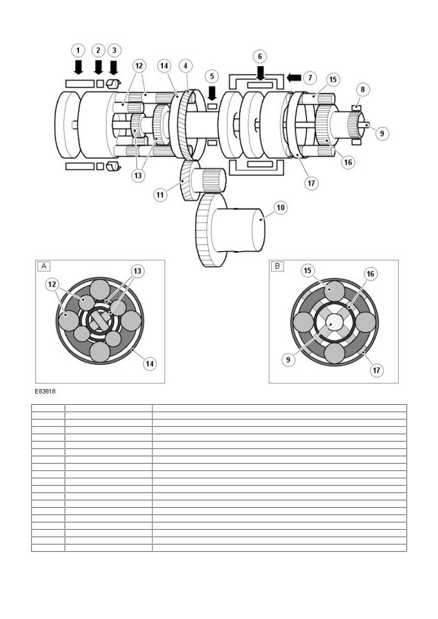
PLANETARY GEAR TRAIN
Item
Part Number
Description
A
-
Double web planetary gear train - Rear
B
-
Single web planetary gear train - Front
1
-
Clutch C2
2
-
Brake B2
3
-
Free wheel clutch F2
4
-
Counter drive gear
5
-
Brake B1
6
-
Clutch C1
7
-
Clutch C3
8
-
Fluid pump
9
-
Input shaft
10
-
Differential gear assembly
11
-
Counter gear assembly
12
-
Pinion gears
13
-
Sun gears
14
-
Ring gear
15
-
Pinion gear
16
-
Sun gears
17
-
Ring gear
The planetary gear trains used on the AW F21 transmission comprise a single web planetary gear train and a double web
planetary gear train. These gear trains are known as Ravignaux type gear trains and together produce the six forward
gears and the one reverse gear.
Engine torque is transferred, via operation of single or combinations of clutches to the two planetary gear trains. Both gear
trains are controlled by reactionary inputs from brake clutches to produce the six forward gears and one reverse gear. The
ratios are as follows:
Gear
1st
2nd
3rd
4th
5th
6th
Reverse
Ratio
4.148
2.370
1.556
1.155
0.859
0.686
3.394
POWER FLOWS
Operation of the transmission is controlled by the TCM which electrically activates various solenoids to control the
transmission gear selection. The sequence of solenoid activation is based on programmed information in the TCM memory
and physical transmission operating conditions such as vehicle speed, throttle position, engine load and selector lever
position.
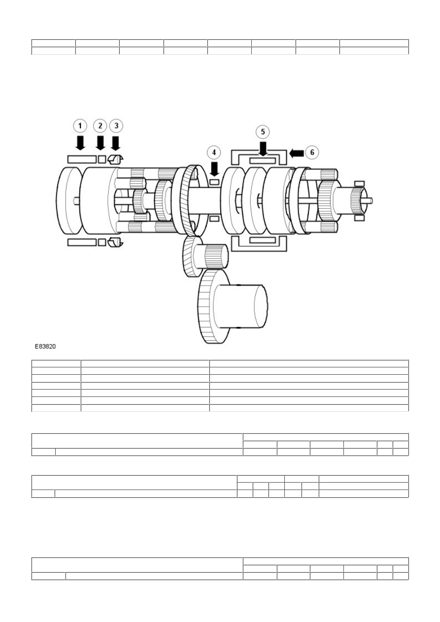
Item
Part Number
Description
1
-
Clutch - C2
2
-
Brake - B2
3
-
One-way clutch - F1
4
-
Brake - B1
5
-
Clutch - C1
6
-
Clutch - C3
Power Flow - 1st Gear Engine Braking
Solenoid Operation
Transmission Selector Lever Position
Solenoid
SLC 1
SLC 2
SLC 3
SLB 1
S1
S2
D
Engine Brake
-
X
X
X
X
X
X = Operating
Clutch and Brake Operation
Transmission Selector Lever Position
Clutch
Brake
One-Way clutch
C1
C2
C3
B1
B2
F1
D
Engine Brake
X
-
-
-
X
X
X = Operating
When the engine brake is active, driving force is transmitted to the transmission from the road wheels, via the power
transfer unit. The rear planetary carrier is locked from clockwise rotation by the one-way clutch (F1) and brake (B2). This
results in torque from the wheels being transmitted directly to the engine, providing engine braking.
Power Flow - 1st Gear
Solenoid Operation
Transmission Selector Lever Position
Solenoid
SLC 1
SLC 2
SLC 3
SLB 1
S1
S2
D
1st Gear
-
X
X
X
-
-
X = Operating
Нет комментариевНе стесняйтесь поделиться с нами вашим ценным мнением.
Текст