Frelander 2. Manual — part 405

DTC
Description
Possible Cause
Action
P210177 Throttle actuator control
motor circuit
range/performance
Throttle body
contaminated/sticking
Throttle actuator control motor
failure
Check the throttle body condition and
operation. Clean the throttle body and
recheck. Install a new throttle body as
necessary.
REFER to:
Throttle Body
(303-04A Fuel
Charging and Controls - I6 3.2L Petrol,
Removal and Installation).
P210300 Throttle actuator control
motor circuit high
Throttle actuator control motor
circuit: short circuit to power
Throttle actuator control motor
failure
Check the throttle motor and circuits. Refer
to the electrical guides. Install a new
throttle body as necessary.
REFER to:
Throttle Body
(303-04A Fuel
Charging and Controls - I6 3.2L Petrol,
Removal and Installation).
P211800 Throttle actuator control
motor current
range/performance
Throttle actuator control motor
circuit: short circuit to power
Throttle actuator control motor
circuit: short circuit to ground
Throttle actuator control motor
circuit: short circuit to power
Throttle actuator control motor
failure
Check the throttle motor and circuits. Refer
to the electrical guides. Install a new
throttle body as necessary.
REFER to:
Throttle Body
(303-04A Fuel
Charging and Controls - I6 3.2L Petrol,
Removal and Installation).
P211900 Throttle actuator control
throttle body
range/performance
Throttle body
contaminated/sticking
Check the condition and operation of the
throttle body. Rectify as necessary. Install a
new throttle body as necessary.
REFER to:
Throttle Body
(303-04A Fuel
Charging and Controls - I6 3.2L Petrol,
Removal and Installation).
P213562 Accelerator pedal position
sensor A/B voltage
correlation
Accelerator pedal position (APP)
sensor signal circuit: open
circuit
Accelerator pedal position (APP)
sensor signal circuit: short
circuit to ground
Accelerator pedal position (APP)
sensor signal circuit: short
circuit to power
Accelerator pedal position (APP)
sensor fault
Carry out a complete vehicle read for related
DTCs. Check the APP sensor and circuits.
Refer to the electrical guides. Rectify as
necessary.
P213800 Throttle/Pedal Position
Sensor/Switch D/E Voltage
Correlation
Accelerator Pedal plausibility -
plausibility violated
Refer to electrical circuit diagrams and check
accelerator pedal circuits for short, open
circuit faults. Check/install new pedal as
required
P213827 Throttle/Pedal Position
Sensor/Switch D/E Voltage
Correlation
Accelerator Pedal plausibility -
dynamic plausibility violated
Refer to electrical circuit diagrams and check
accelerator pedal circuits for short, open
circuit faults. Check/install new pedal as
required
P213828 Throttle/Pedal Position
Sensor/Switch D/E Voltage
Correlation
Accelerator Pedal plausibility -
extended plausibility violated
Refer to electrical circuit diagrams and check
accelerator pedal circuits for short, open
circuit faults. Check/install new pedal as
required
Speed Control - I6 3.2L Petrol - Speed Control Switch
Removal and Installation
Removal
Disconnect the battery ground cable.
Refer to:
Specifications
(414-00 Battery and Charging System -
General Information, Specifications).
1.
Make the SRS system safe.
Refer to: Supplemental Restraint System (SRS) Depowering and
Repowering (501-20, General Procedures).
2.
Remove the driver air bag module.
Refer to:
Driver Air Bag Module
(501-20B Supplemental Restraint
System, Removal and Installation).
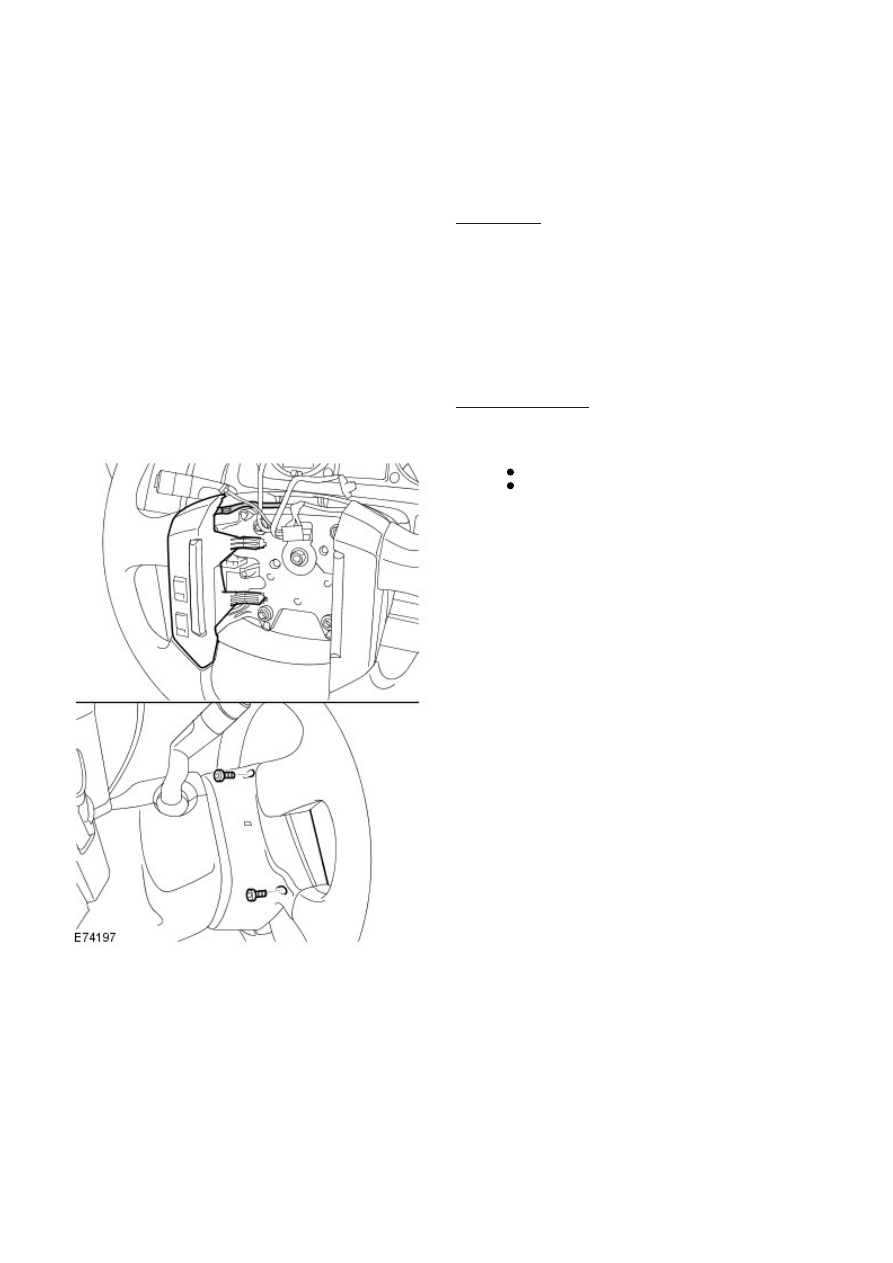
3.
Remove the 2 Torx screws.
Disconnect the electrical connector.
4.
Installation
To install, reverse the removal procedure.
1.
Speed Control - I6 3.2L Petrol - Speed Control Actuator
Removal and Installation
Removal
Remove the accelerator pedal assembly.
Refer to:
Accelerator Pedal
(310-02 Acceleration Control, Removal
and Installation).
1.
Installation
Install the accelerator pedal assembly.
Refer to:
Accelerator Pedal
(310-02 Acceleration Control, Removal
and Installation).
1.
Speed Control - I6 3.2L Petrol - Speed Control Deactivator Switch
Removal and Installation
Removal
Right-hand drive vehicles
Remove the cover and disconnect the battery ground cable.
Refer to:
Specifications
(414-00 Battery and Charging System -
General Information, Specifications).
1.
Remove the stoplamp switch.
Refer to:
Stoplamp Switch
(417-01 Exterior Lighting, Removal and
Installation).
2.
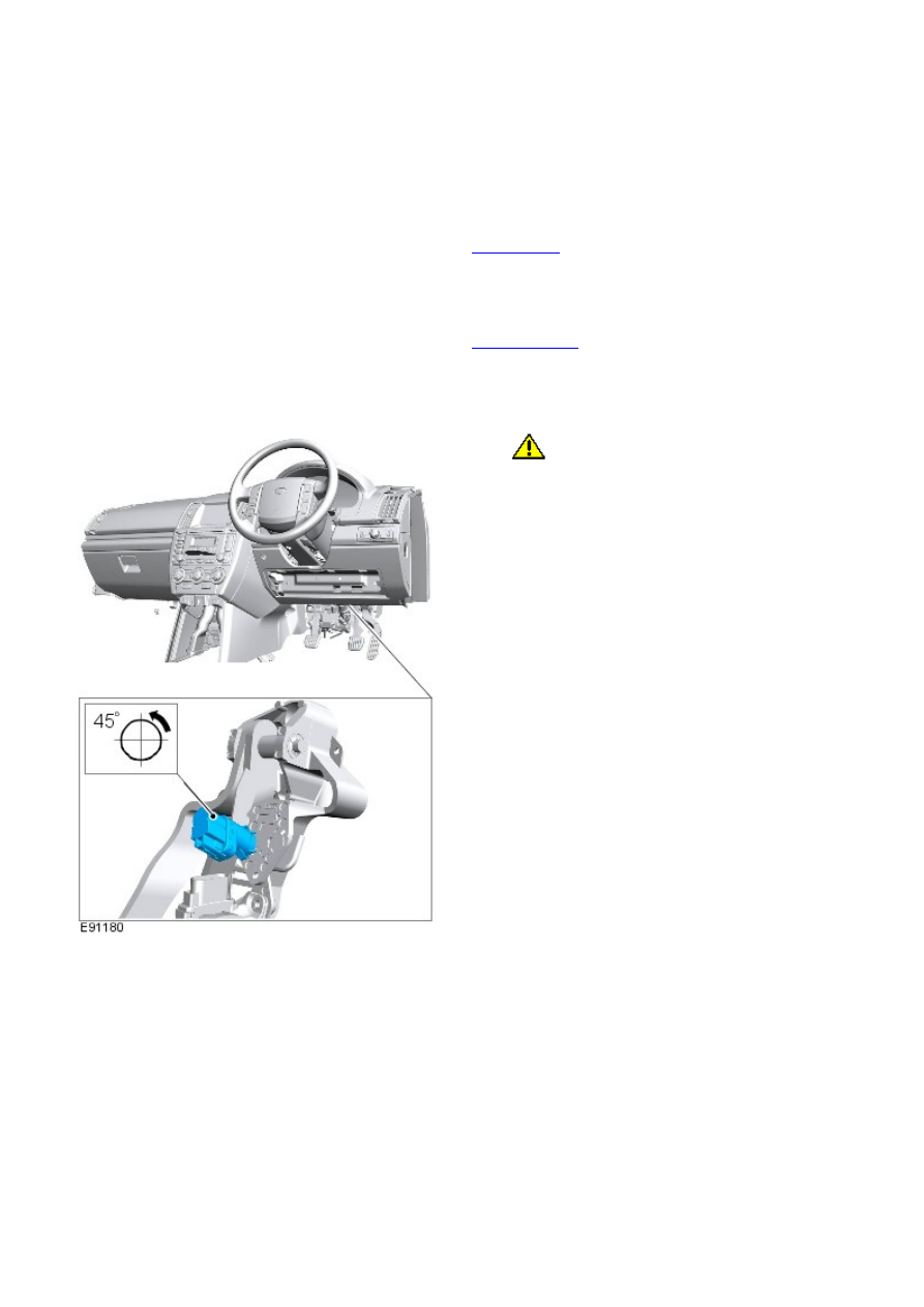
All vehicles
3.
CAUTION: The switch has a latching device that
only allows the switch to be removed or installed when
the switch plunger is depressed.
• NOTE: RHD illustration shown, LHD is similar.
3.
Installation
To install, reverse the removal procedure.
1.
Нет комментариевНе стесняйтесь поделиться с нами вашим ценным мнением.
Текст