Frelander 2. Manual — part 493
Module Communications Network - Central Junction Box (CJB)
Removal and Installation
Removal
If renewing the CJB, use Land Rover approved diagnostic equipment
to interrogate the module and upload the stored data, prior to
removal of the CJB.
1.
Disconnect the battery ground cable.
Refer to:
Specifications
(414-00 Battery and Charging System -
General Information, Specifications).
2.
Remove the glove compartment.
Refer to:
Glove Compartment
(501-12 Instrument Panel and
Console, Removal and Installation).
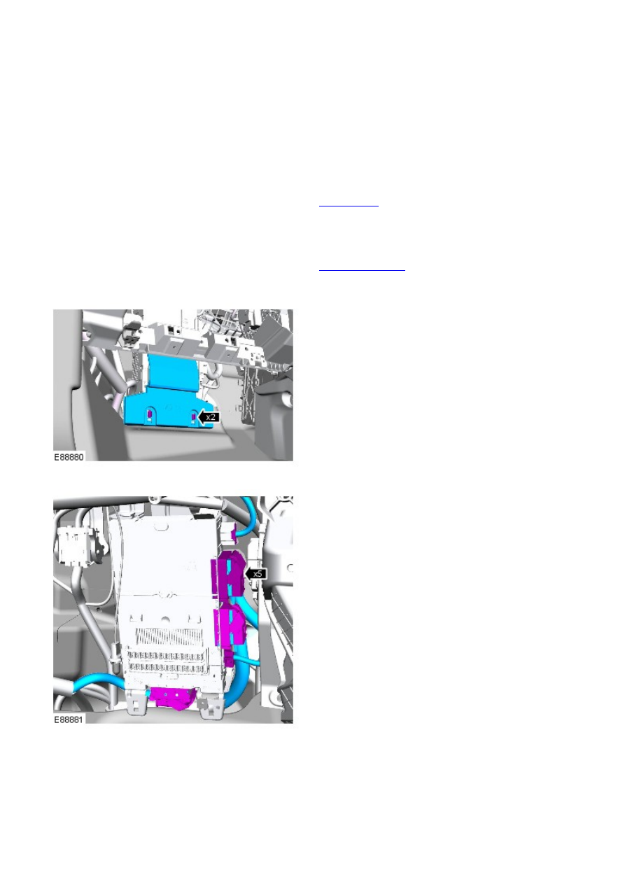
3.
4.
5.
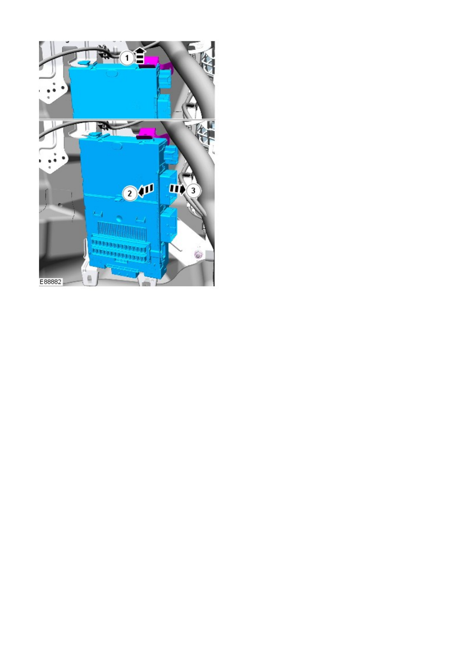
6.
Installation
1. NOTE: The Central Junction Box is pre-programmed by Land Rover
and therefore no IDS connection is required. Original remote keys
will function. Any additional remote keys will no longer function.
To install, reverse the removal procedure.
1.
Module Communications Network - Battery Junction Box (BJB)TD4 2.2L
Diesel
Removal and Installation
Removal
Remove the bumper armature.
Refer to:
Front Bumper
(501-19 Bumpers, Removal and Installation).
1.
Remove the air cleaner housing.
Refer to:
Air Cleaner
(303-12A Intake Air Distribution and Filtering -
I6 3.2L Petrol, Removal and Installation).
2.
Remove the secondary bulkhead center panel.
Refer to:
Secondary Bulkhead Center Panel - TD4 2.2L Diesel
(501-02 Front End Body Panels, Removal and Installation).
3.
Remove the brake booster.
Refer to:
Brake Booster
(206-07 Power Brake Actuation, Removal
and Installation).
4.
Remove the ABS module.
Refer to:
Anti-Lock Brake System (ABS) Module
(206-09A Anti-Lock
Control, Removal and Installation).
5.
Remove the fuel fired booster heater.
Refer to:
Fuel Fired Booster Heater
(412-02B Auxiliary Climate
Control, Removal and Installation).
6.
Remove both headlamps.
Refer to:
Headlamp Assembly
(417-01 Exterior Lighting, Removal
and Installation).
7.
Remove the engine upper support insulator.
Refer to:
Engine Upper Support Insulator
(303-01A Engine - I6 3.2L
Petrol, Removal and Installation).
8.
Remove the glove compartment lid.
Refer to:
Glove Compartment
(501-12 Instrument Panel and
Console, Removal and Installation).
9.
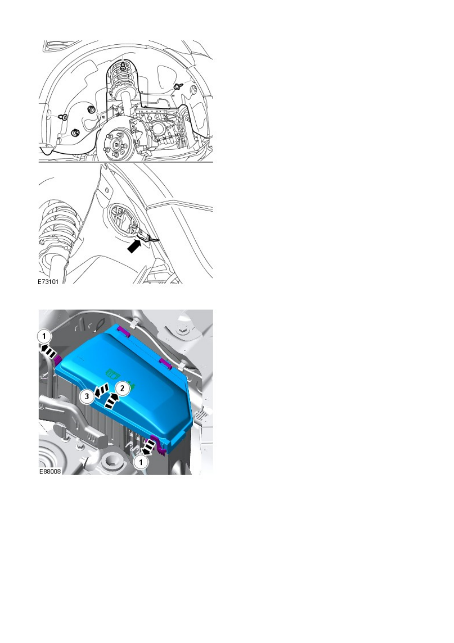
10. NOTE: RHD illustration shown, LHD is similar.
Remove the LH fender splash shield.
10.
11.
Нет комментариевНе стесняйтесь поделиться с нами вашим ценным мнением.
Текст