Frelander 2. Manual — part 639
Front End Sheet Metal Repairs - Suspension Top Mount
Removal and Installation
Removal
• NOTE: The suspension top mount is serviced as a separate weld-on panel.
• NOTE: The service panel is not fully welded.
• NOTE: The panel is serviced less its weld studs
1. The suspension top mount is replaced in conjunction with:
Front bumper cover
Front bumper armature
Hood
Hood latch panel
Both front fenders
Fender apron upper panel
Fender apron panel
Instrument panel
• NOTE: It is also necessary to remove the engine and suspension as an assembly.
2. For additional information relating to this repair procedure
please see the following:
For additional information, refer to:
Body and Frame
(501-26
Body Repairs - Vehicle Specific Information and Tolerance
Checks, Description and Operation) /
Standard Workshop Practices
(100-00 General Information,
Description and Operation).
3. Remove the fender apron panel.
For additional information, refer to:
Fender Apron Panel
(501-27 Front End Sheet Metal Repairs, Removal and
Installation).
4. Remove the instrument panel.
For additional information, refer to:
Instrument Panel - TD4
2.2L Diesel
(501-12 Instrument Panel and Console, Removal
and Installation).
5. Remove the rocker panel inner trim panel.
6. Remove the B-pillar lower trim panel.
For additional information, refer to:
B-Pillar Lower Trim Panel
(501-05 Interior Trim and Ornamentation, Removal and
Installation).
7. Remove the engine and front suspension as an assembly.
8. RH Side: Remove the pedal box.
9. RH Side: Remove the brake master cylinder.
For additional information, refer to:
Brake Master Cylinder
(206-06 Hydraulic Brake Actuation, Removal and Installation).
10. Release and lay aside the carpet and insulating material at
the inner bulkhead.
11. Release and lay aside the wiring harness.
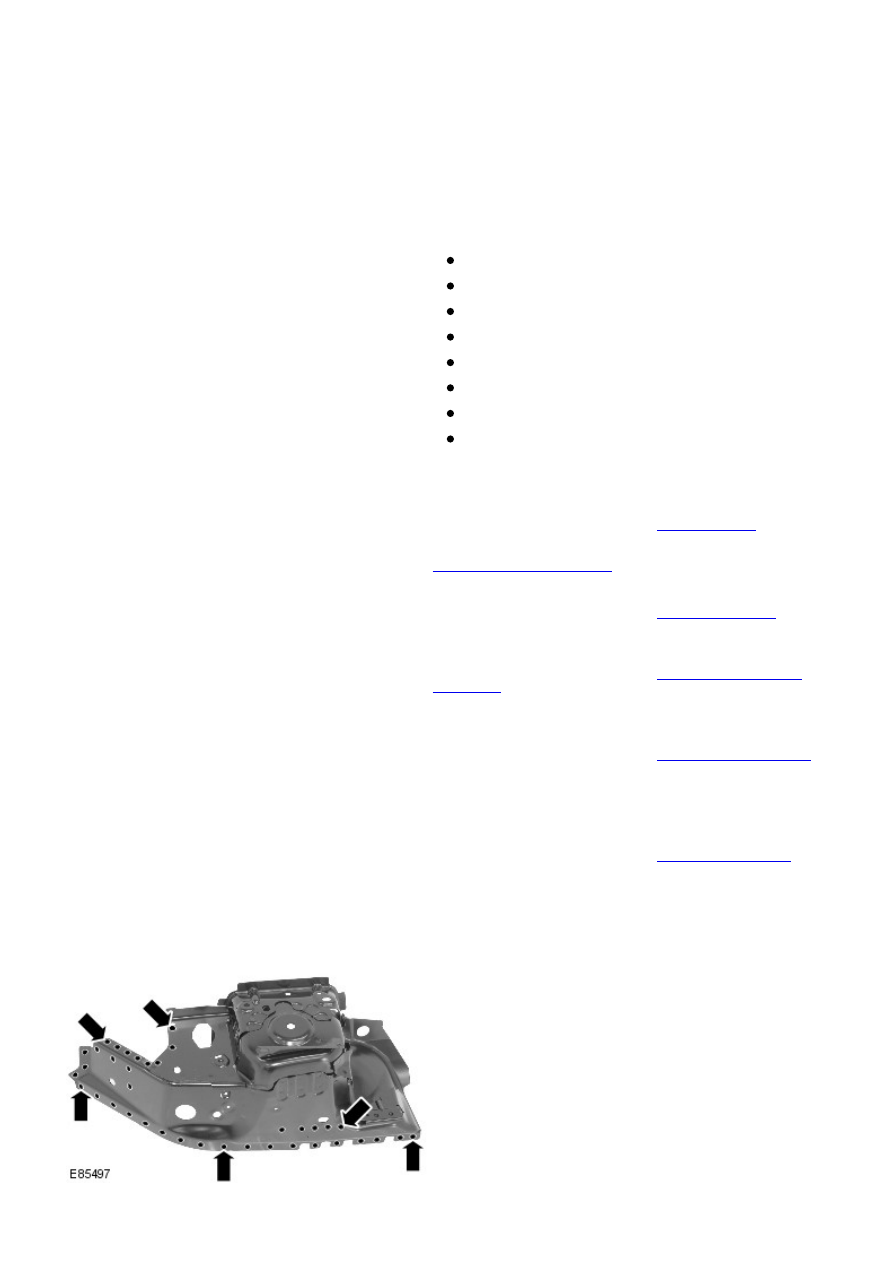
12. Mill out the spot welds.
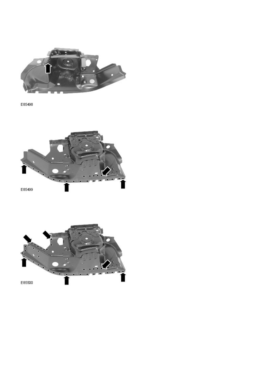
13. Separate the joints and remove the old panel.
Installation
1. Prepare and MIG plug weld the new panel in the area
illustrated, where it is not fully welded.
2. Prepare the old and new panel joint surfaces.
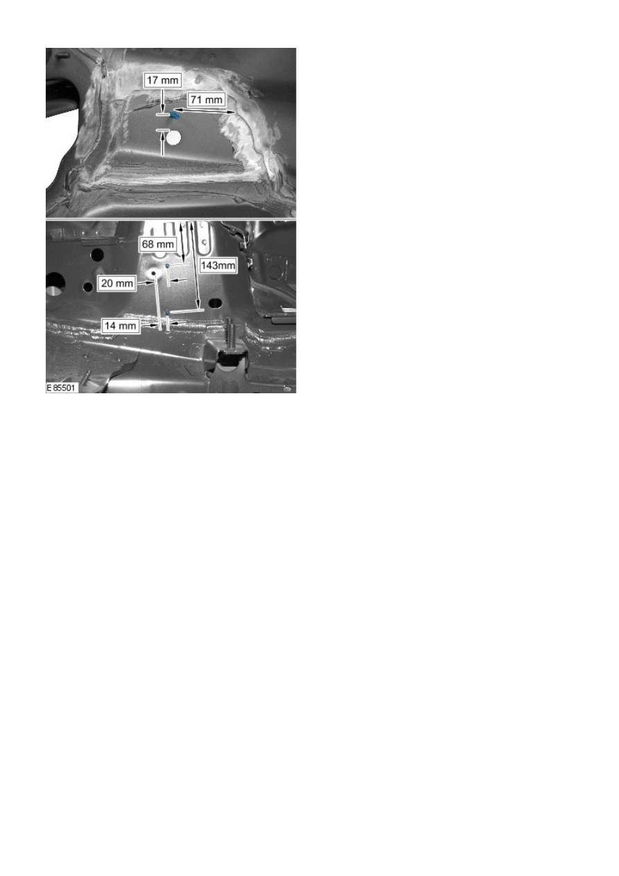
3. Drill holes in the new panel ready for MIG plug welding.
4. Offer up the new panel and clamp into position. Check
alignment, if correct, proceed to next step, if not, rectify and
recheck before proceeding.
5. MIG Plug weld.
6. Install weld studs.
7. Dress all welded joints.
8. The installation of associated panels and mechanical
components is the reverse of removal.
Front End Sheet Metal Repairs - Front Side Member Section
Removal and Installation
Removal
• NOTE: The front side member section is cut from the front side member service panel.
• NOTE: The RH section is slightly shorter than the LH due to the location of the engine mounting.
• NOTE: Due to the combined thickness of the panels, it is recommended that spot welds are replaced with MIG plug welds
in this repair.
1. The front side member section is replaced in conjunction with:
Front bumper cover
Front bumper armature
Hood latch panel
Both front fenders
Front bumper mounting
• NOTE: It is also necessary to remove the engine and suspension as an assembly.
2. For additional information relating to this repair procedure
please see the following:
For additional information, refer to:
Body and Frame
(501-26
Body Repairs - Vehicle Specific Information and Tolerance
Checks, Description and Operation) /
Standard Workshop Practices
(100-00 General Information,
Description and Operation).
3. Remove the front bumper mounting.
For additional information, refer to:
Front Bumper Mounting
(501-27 Front End Sheet Metal Repairs, Removal and
Installation).
4. Remove the radiator cooling pack.
For additional information, refer to:
Radiator
(303-03A Engine
Cooling - I6 3.2L Petrol, Removal and Installation).
5. Remove the engine and front suspension as an assembly.
6. LH Side: Remove the air intake pipe.
7. LH Side: Release the battery junction box and position aside.
8. RH Side: Remove the windshield washer reservoir.
For additional information, refer to:
Windshield Washer
Reservoir
(501-16 Wipers and Washers, Removal and
Installation).
9. Release and lay aside the wiring harness.
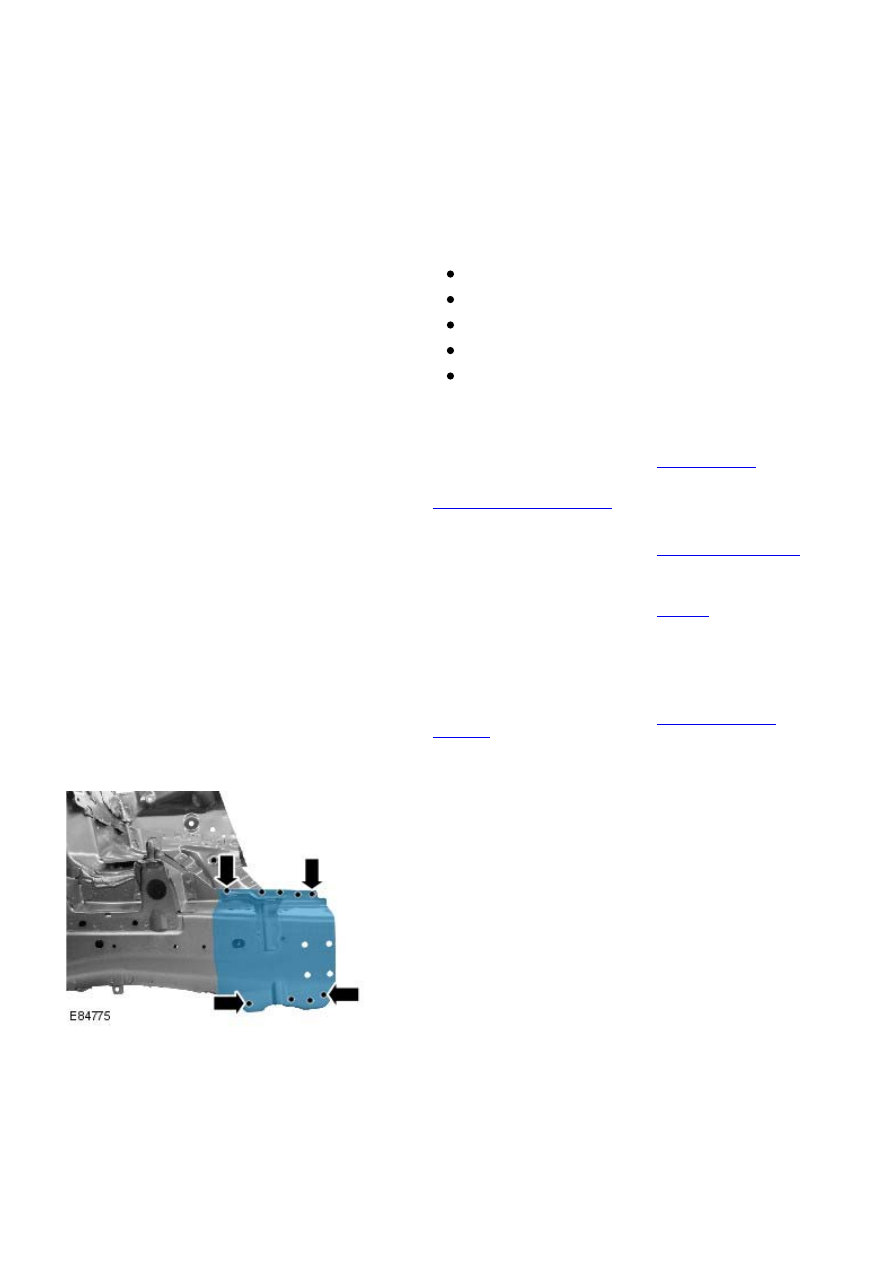
10. Mill out the spot welds.
Нет комментариевНе стесняйтесь поделиться с нами вашим ценным мнением.
Текст