Discovery 2. Manual — part 606
FRONT SUSPENSION
DESCRIPTION AND OPERATION
60-21
A road speed signal is transmitted to the ACE ECU as a pulsed digital signal from the Self-levelling/Anti-lock Braking
System (SLABS) ECU. The road speed signal is used by the ACE ECU for on and off-road roll compensation.
When reverse gear is selected, an input is received from the reverse lamp switch. When the ACE ECU detects that
reverse gear has been selected, the ACE system reverts to a 'locked bars' condition until reverse gear is disengaged.
The diagnostic connection allows diagnostic interrogation of the ACE ECU. The diagnostic socket allows diagnostic
equipment to be connected to interrogate the ACE ECU for fault codes.
When system faults are detected by the ECU, the ACE warning lamp in the instrument pack is illuminated by the ECU
continuously in amber for minor faults or flashing red with an audible warning for faults which require the driver to stop
the vehicle immediately.
The ACE ECU supplies a control current to the pressure control valve in the valve block. The current supplied by the
ECU is determined by a number of input signals from the upper and lower accelerometers, road speed etc.. The
pressure control valve controls the hydraulic pressure supplied to the actuators proportional to the current supplied
by the ECU.
Power is supplied to the two solenoid operated directional control valves (DCV's) in the valve block by the ECU.
Together, the DCV's control the direction of flow of hydraulic fluid to the actuators. When the ECU supplies power to
the solenoids the valves open allowing hydraulic fluid to flow to the actuators. When power is removed the valves
close.
The pressure transducer in the valve block receives a 5 V supply from the ECU. The pressure transducer measures
hydraulic pressures in the range of 0 to 180 bar (0 to 2610 lbf.in
2
) and returns a linear output voltage to the ECU
dependent on hydraulic pressure.
The ECU supplies a 5 V current to each of the accelerometers. Each accelerometer is capable of measuring lateral
acceleration in the range of
±
1.10 g. An analogue input to the ECU of between 0.5 and 4.5 V relative to the lateral
acceleration sensed is returned by each accelerometer. The ECU processes the two signals received to produce a
'pure' lateral acceleration signal which is then used as the main control signal for the ACE system.
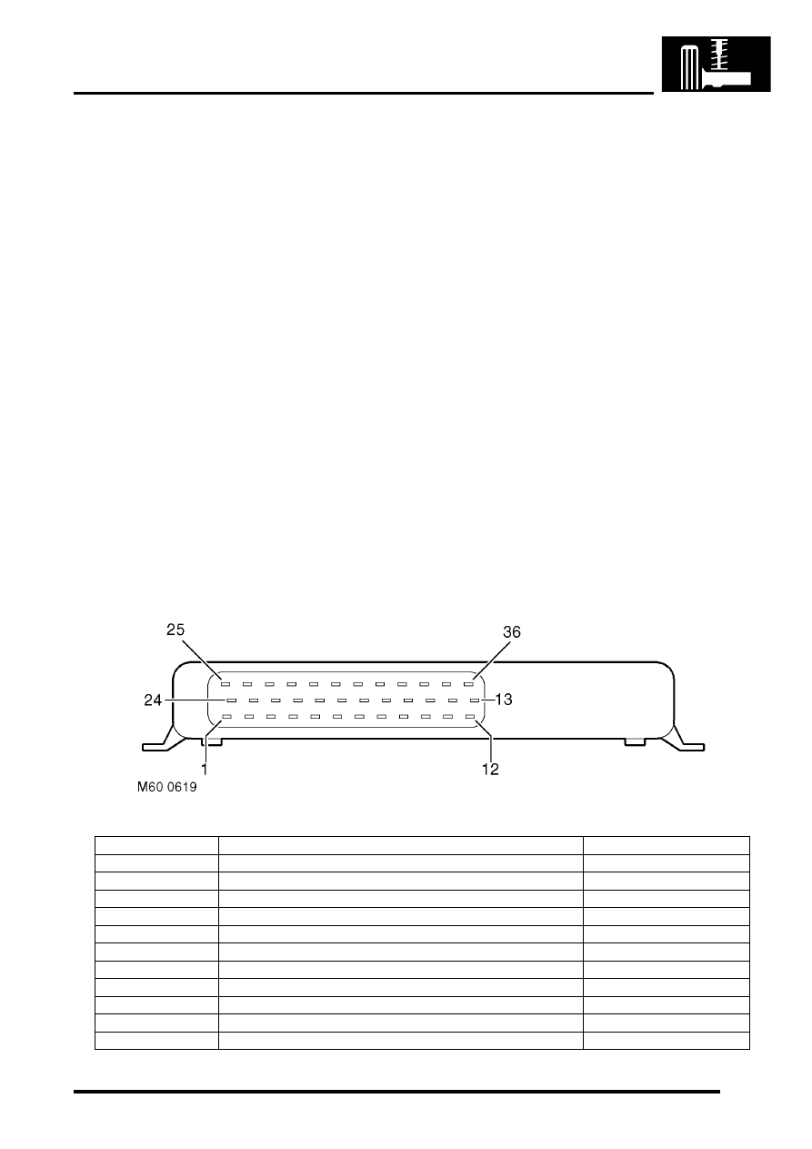
ACE ECU connector pin details
Pin No.
Description
Input/Output
1
Not used
-
2
Not used
-
3
Spare
Input
4
Not used
-
5
Road speed
Input
6
ARC relay
Output
7 to 9
Not used
-
10
K line (diagnostics)
-
11
Ignition switch
Input
12
Accelerometer - lower (supply)
Output
13
Pressure transducer (supply)
Output
FRONT SUSPENSION
60-22
DESCRIPTION AND OPERATION
Failure modes
Failures where the vehicle can still be driven safely are indicated by the ACE warning lamp illuminating continuously
with an amber colour. The amber warning lamp will remain illuminated until the ignition is turned off. For all faults the
warning lamp will only illuminate again if the fault is still present. Failures which require the driver to stop the vehicle
immediately are indicated by the ACE warning lamp flashing with a red colour and an audible warning. All faults are
recorded by the ACE ECU and can be retrieved with diagnostic equipment.
The following tables show the type of system failures and their effects on the system operation. Torsion bar 'floppy'
means that fluid is allowed to circulate freely through the system. With no pressure in the actuators the torsion bar will
have no effect on vehicle roll. 'Locked bars' means that all pump flow is directed through the valve block and returns
to the reservoir. Both DCV's close and fluid is trapped in the actuators but can flow from one actuator to the other via
the valve block. In this condition the torsion bar will perform similar to a conventional anti-roll bar, resisting roll but still
allowing the axles to articulate.
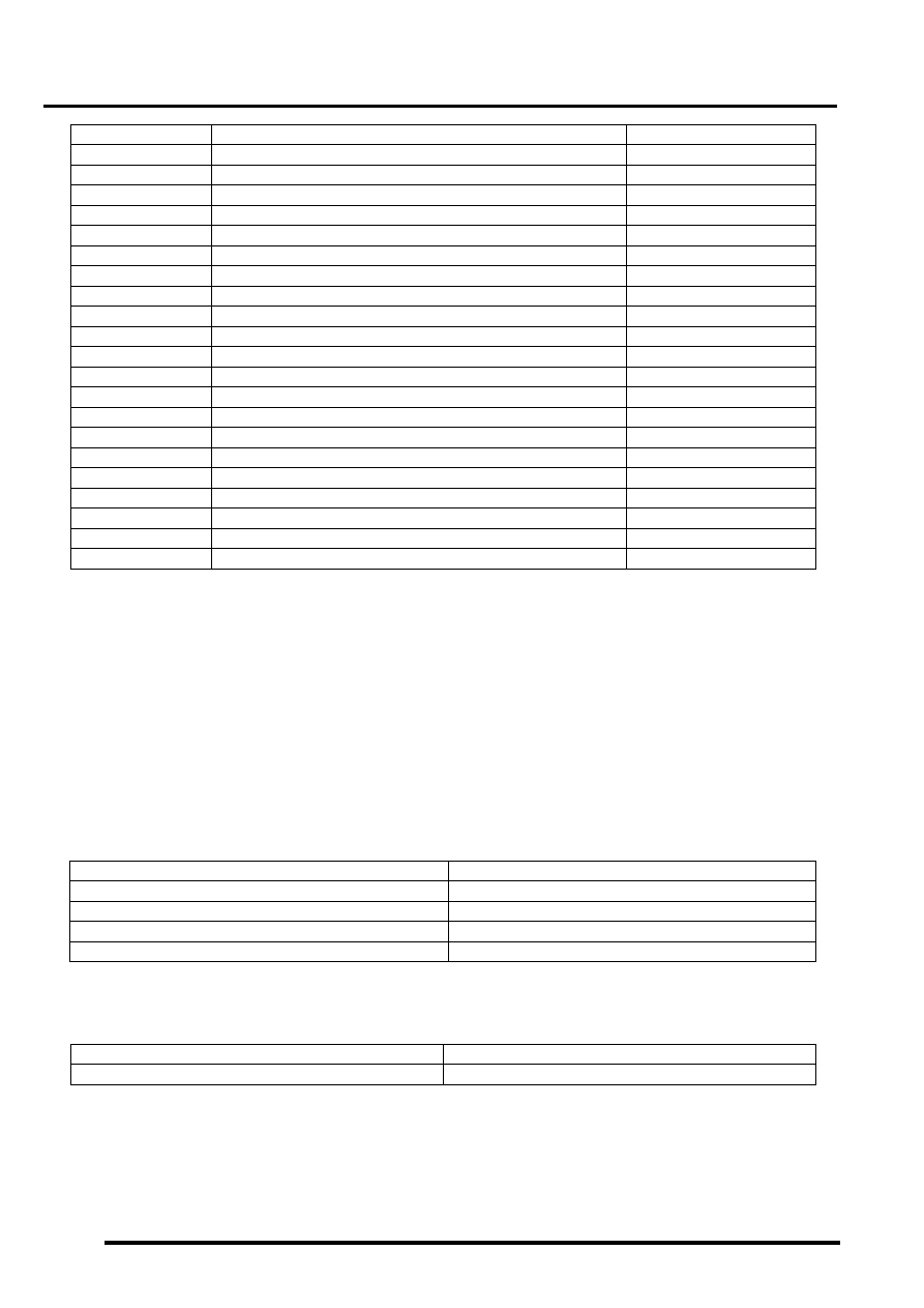
Acceleration sensors
Pressure transducer
14
Reverse switch
Input
15
Accelerometer - lower (signal)
Input
16
Pressure transducer (signal)
Input
17
Accelerometer - upper (signal)
Input
18
Accelerometer - upper (supply)
Output
19
Engine speed
Input
20
Main earth 1
-
21
Pressure transducer (earth)
Input
22
DCV 2 (earth)
Input
23
DCV 1 (earth)
Input
24
DCV 1 & 2 (supply)
Output
25
Pressure control valve (earth)
Input
26
Not used
-
27
Pressure control valve (supply)
Output
28
Main supply (+ V Batt)
Input
29 to 31
Not used
-
32
Main earth 2
-
33
Accelerometer - lower (signal)
Input
34
Accelerometer - upper (signal)
Input
35
Not used
-
36
Warning lamp
Output
Failure
Effect
Valve stuck closed
No ACE control
Short circuit - Ground
No ACE control
Short circuit - VBatt
No ACE control
Loose sensor
Erractic ACE activity when driving in straight line
Failure
Effect
Short circuit - VBatt
Large sensor dead band - possible random movements
Pin No.
Description
Input/Output
FRONT SUSPENSION
DESCRIPTION AND OPERATION
60-23
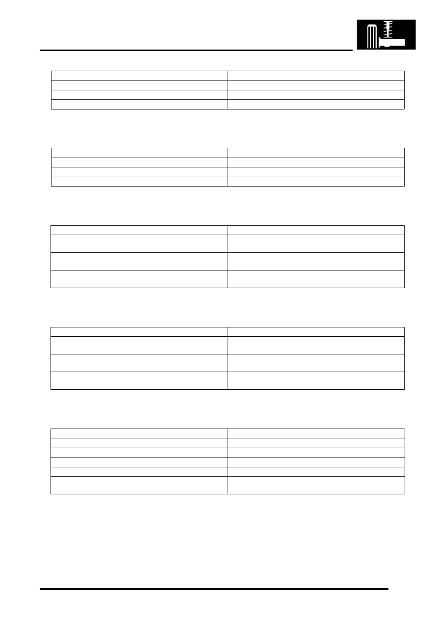
Road speed signal
Engine speed signal
Reverse gear signal
Ignition ON signal
Pressure control valve failure
Failure
Effect
Open circuit
No ACE control - 'Locked bars' condition
Short circuit - Ground
No ACE control - 'Locked bars' condition
Short circuit - VBatt
No ACE control - 'Locked bars' condition
Failure
Effect
Open circuit
No ACE control - 'Locked bars' condition
Short circuit - Ground
No ACE control - 'Locked bars' condition
Short circuit - VBatt
No ACE control - 'Locked bars' condition
Failure
Effect
Open circuit
No reverse signal to ECU. ACE active in reverse, may give
abnormal handling when reversing
Short circuit - Ground
No reverse signal to ECU. ACE active in reverse, may give
abnormal handling when reversing
Short circuit - VBatt
Permanent reverse signal to ECU. Permanent 'Locked
bars' condition
Failure
Effect
Open circuit
ECU does not receive ignition ON signal. No ARC control,
'Locked bars' condition
Short circuit - Ground
ECU does not receive ignition ON signal. No ARC control,
'Locked bars' condition
Short circuit - VBatt
Permanent ignition ON signal to ECU. Possibility of flat
battery
Failure
Effect
Open circuit
No ACE control
Short circuit - Ground
No ACE control
Short circuit - VBatt
No ACE control
Valve stuck open
No ACE control
Valve stuck closed
Maximum system pressure - no proportional control.
Pressure relief valve operating at 185 bar (2683 lbf.in
2
)

FRONT SUSPENSION
60-24
DESCRIPTION AND OPERATION
Directional control valves
Failure
Effect
DCV 1
DCV 2
Valve open or stuck open
Valve open or stuck open
No ACE control - Anti-roll bars floppy
Valve closed or stuck closed Valve closed stuck closed
No ACE control - 'Locked bars' condition (default)
Valve open or stuck open
Valve closed or stuck closed Vehicle leans to left when pressure is applied to actuators
Valve closed or stuck closed Valve open or stuck open
Vehicle leans to right when pressure is applied to actuators
Нет комментариевНе стесняйтесь поделиться с нами вашим ценным мнением.
Текст