Discovery 2. Manual — part 76
ENGINE MANAGEMENT SYSTEM - V8
DESCRIPTION AND OPERATION 18-2-33
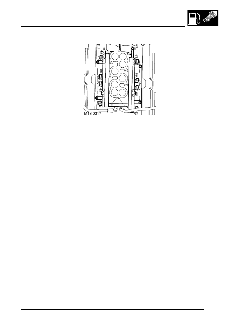
Fuel injectors
The fuel injectors are located beneath the air inlet manifold. They utilise an electrical solenoid to lift the injector needle
off its seat to allow fuel injection to take place. The fuel injectors provide excellent fuel atomisation in the lower portion
of the inlet manifold, the air/fuel mixture can then be drawn into the cylinders to give good combustion characteristics
and therefore excellent driveability.
There are eight fuel injectors one per cylinder that the ECM operates sequentially. All the injectors are fed from a
common fuel rail as part of the returnless fuel system. Fuel pressure is maintained at a constant 3.5 bar (52 lbf.in
2
) by
a regulator that is integral with the fuel pump.
FUEL DELIVERY SYSTEM - V8, DESCRIPTION AND OPERATION, Description.
Input/Output
All eight fuel injectors are supplied with battery voltage via fuse number 1 located in engine compartment fuse box.
The ECM controls the individual earth path for each injector via its own pin at connector C0636 of the ECM multiplug.
This facility allows the ECM to control the fuel injectors so that sequential fuel injection can take place.
Typical hot engine injector pulse width values:
l
Idle = 2.5 ms.
l
Peak torque (3000 rev/min) = 7 ms The ECM controls injector earth as follows:
l
Cylinder No 1 - pin 41 of connector C0636 of the ECM multiplug.
l
Cylinder No 2 - pin 1 of connector C0636 of the ECM multiplug.
l
Cylinder No 3 - pin 27 of connector C0636 of the ECM multiplug.
l
Cylinder No 4 - pin 40 of connector C0636 of the ECM multiplug.
l
Cylinder No 5 - pin 2 of connector C0636 of the ECM multiplug.
l
Cylinder No 6 - pin 15 of connector C0636 of the ECM multiplug.
l
Cylinder No 7 - pin 14 of connector C0636 of the ECM multiplug.
l
Cylinder No 8 - pin 28 of connector C0636 of the ECM multiplug.
Individual injectors can be measured for resistance using a multimeter. An acceptable injector resistance is as follows:
l
14.5
±
0.7 ohms at 20
°
C (68
°
F).
The fuel injectors can fail in the following ways or supply incorrect signal:
l
Injector actuator open circuit.
l
Short circuit to vehicle supply.
l
Short circuit to vehicle earth.
l
Blocked injector.
l
Restricted injector.
l
Low fuel pressure.

ENGINE MANAGEMENT SYSTEM - V8
18-2-34 DESCRIPTION AND OPERATION
In the event of fuel injector signal failure any of the following symptoms may be observed:
l
Rough running.
l
Difficult starting.
l
Engine misfire.
l
Possible catalyst damage.
l
High emissions.
l
Adaptive fuelling disabled.
l
Adaptive idle speed control disabled.
The ECM performs three types of fuel injector diagnostic check:
l
Output short circuit to earth
l
Output short circuit to battery voltage
l
Output open circuit
Should a malfunction of the component occur the following fault codes may be evident and can be retrieved by
TestBook:
P Code
J2012 Description
Land Rover Description
P0201
Injection circuit malfunction - cylinder 1
Injector 1 open circuit
P0261
Cylinder 1 injector circuit low
Injector 1 short circuit to earth
P0262
Cylinder 1 injector circuit high
Injector 1 short circuit to battery supply
P0301
Cylinder 1 misfire detected
Injector 1 excess emissions/catalyst damaging level of
misfire
P0202
Injection circuit malfunction - cylinder 2
Injector 2 open circuit
P0264
Cylinder 2 injector circuit low
Injector 2 short circuit to earth
P0265
Cylinder 2 injector circuit high
Injector 2 short circuit to battery supply
P0302
Cylinder 2 misfire detected
Injector 2 excess emissions/catalyst damaging level of
misfire
P0203
Injection circuit malfunction - cylinder 3
Injector 3 open circuit
P0267
Cylinder 3 injector circuit low
Injector 3 short circuit to earth
P0268
Cylinder 3 injector circuit high
Injector 3 short circuit to battery supply
P0303
Cylinder 3 misfire detected
Injector 3 excess emissions/catalyst damaging level of
misfire
P0204
Injection circuit malfunction - cylinder 4
Injector 4 open circuit
P0270
Cylinder 4 injector circuit low
Injector 4 short circuit to earth
P0271
Cylinder 4 injector circuit high
Injector 4 short circuit to battery supply
P0304
Cylinder 4 misfire detected
Injector 4 excess emissions/catalyst damaging level of
misfire
P0205
Injection circuit malfunction - cylinder 5
Injector 5 open circuit
P0273
Cylinder 5 injector circuit low
Injector 5 short circuit to earth
P0274
Cylinder 5 injector circuit high
Injector 5 short circuit to battery supply
P0305
Cylinder 5 misfire detected
Injector 5 excess emissions/catalyst damaging level of
misfire
P0206
Injection circuit malfunction - cylinder 6
Injector 6 open circuit
P0276
Cylinder 6 injector circuit low
Injector 6 short circuit to earth
P0277
Cylinder 6 injector circuit high
Injector 6 short circuit to battery supply
P0306
Cylinder 6 misfire detected
Injector 6 excess emissions/catalyst damaging level of
misfire
P0207
Injection circuit malfunction - cylinder 7
Injector 7 open circuit
P0279
Cylinder 7 injector circuit low
Injector 7 short circuit to earth
P0280
Cylinder 7 injector circuit high
Injector 7 short circuit to battery supply
P0307
Cylinder 7 misfire detected
Injector 7 excess emissions/catalyst damaging level of
misfire
P0208
Injection circuit malfunction - cylinder 8
Injector 8 open circuit
P0282
Cylinder 8 injector circuit low
Injector 8 short circuit to earth
P0283
Cylinder 8 injector circuit high
Injector 8 short circuit to battery supply

ENGINE MANAGEMENT SYSTEM - V8
DESCRIPTION AND OPERATION 18-2-35
P0308
Cylinder 8 misfire detected
Injector 8 excess emissions/catalyst damaging level of
misfire
P0171
System too lean (bank 1)
Multiplication injector adaptive fuelling - lean limit
exceeded LH bank
P0172
System too rich (bank 1)
Multiplication injector adaptive fuelling - rich limit
exceeded LH bank
P0174
System too lean (bank 2)
Multiplication injector adaptive fuelling - lean limit
exceeded RH bank
P0175
System too rich (bank 2)
Multiplication injector adaptive fuelling - rich limit
exceeded RH bank
P1171
System too lean (bank 1)
Additive injector adaptive fuelling - lean limit exceeded
LH bank
P1172
System too rich (bank1)
Additive injector adaptive fuelling - rich limit exceeded
LH bank
P1174
System too lean (bank 2)
Additive injector adaptive fuelling - lean limit exceeded
RH bank
P1175
System too rich (bank 2)
Additive injector adaptive fuelling - rich limit exceeded
RH bank
P0300
Random/multiple cylinder excess emissions
detected
Excess emissions detected on more than one cylinder
P1300
Random/multiple cylinder misfire detected
Catalyst damaging level of misfire on more than one
cylinder
P1319
Misfire detected with low fuel level
P Code
J2012 Description
Land Rover Description
ENGINE MANAGEMENT SYSTEM - V8
18-2-36 DESCRIPTION AND OPERATION
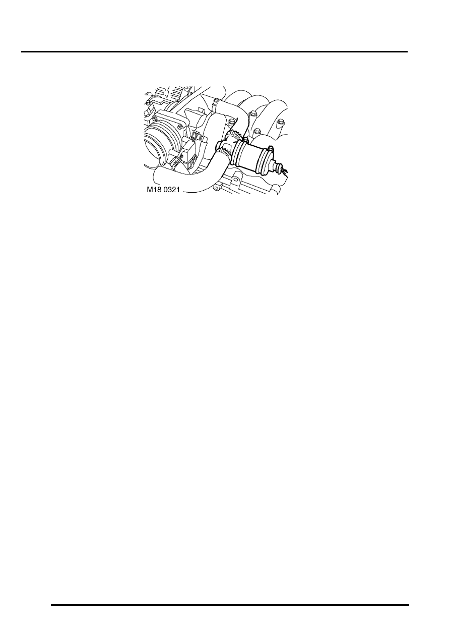
Idle Air Control Valve (IACV) (C0641)
The IACV is located on the side of the air inlet pipe on top of the engine. The IACV is used to maintain good quality
idle speed under all operating conditions.
When an engine is running at idle it is subject to a combination of internal and external loads that can affect idle speed.
These loads include engine friction, water pump, alternator operation, and air conditioning.
The IACV acts as an air bypass valve. The ECM uses the IACV to enable the closed loop idle speed calculation to be
made by the ECM. This calculation regulates the amount of air flow into the engine at idle, therefore compensating
for any internal or external loads that may affect idle speed.
The IACV utilises two coils that use opposing PWM signals to control the position of opening/closing of a rotary valve.
If one of the circuits that supply the PWM signal fails, the ECM closes down the remaining signal preventing the IACV
from working at its maximum/ minimum setting. If this should occur, the IACV automatically resumes a default idle
position. In this condition, the engine idle speed is raised and maintained at 1200 rev/min with no load placed on the
engine.
The idle speed in cold start condition is held at 1200 rev/min in neutral for 20 seconds and ignition timing is retarded
as a catalyst heating strategy. The cold start idle speed and the default idle position give the same engine speed 1200
rev/min, and although they are the same figure they must not be confused with each other as they are set separately
by the ECM.
Note that the rotary valve must not be forced to move by mechanical means. The actuator can not be
serviced; if defective, the entire IACV must be replaced.
Input/Output
The input to the IACV is a 12 volt signal from fuse 2 located in the engine compartment fuse box. The output earth
signal to open and close the actuator is controlled by the ECM as follows:
l
IACV (open signal) - via pin 42 of connector C0636 of the ECM
l
IACV (closed signal) - via pin 43 of connector C0636 of the ECM
The IACV can fail the following ways or supply incorrect signal:
l
Actuator faulty.
l
Rotary valve seized.
l
Wiring loom fault.
l
Connector fault.
l
Intake system air leak.
l
Blocked actuator port or hoses.
l
Restricted or crimped actuator port or hoses.
In the event of an IACV signal failure any of the following symptoms may be observed:
l
Either low or high idle speed.
l
Engine stalls.
l
Difficult starting.
l
Idle speed in default condition.
Нет комментариевНе стесняйтесь поделиться с нами вашим ценным мнением.
Текст