Discovery 2. Manual — part 324

ALARM SYSTEM AND HORN
DESCRIPTION AND OPERATION 86-4-1
Deze pagina werd opzettelijk niet gebruikt
Cette page est intentionnellement vierge
Questa pagina è stata lasciata in bianco di proposito
Diese Seite ist leer
Esta página foi deixada intencionalmente em branco
Esta página fue dejada en blanco intencionalmente
This page is intentionally left blank
ALARM SYSTEM AND HORN
DESCRIPTION AND OPERATION
ALARM SYSTEM AND HORN
86-4-2
DESCRIPTION AND OPERATION
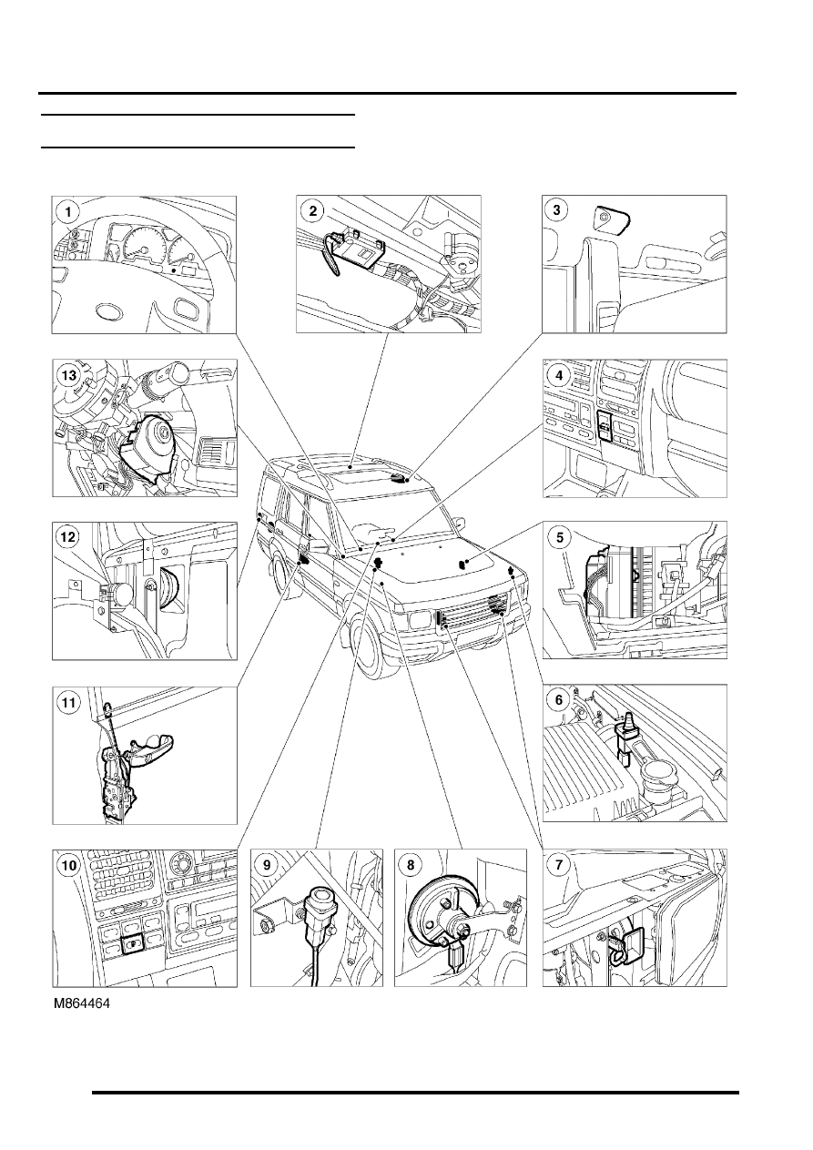
Alarm system component layout
RHD shown, LHD similar

ALARM SYSTEM AND HORN
DESCRIPTION AND OPERATION
86-4-3
1 Theft deterrent LED
2 Receiver
3 Volumetric sensors
4 Central door locking switch
5 Body Control Unit (BCU)
6 Bonnet activated alarm switch
7 Vehicle horn
8 Alarm sounder
9 Fuel cut off switch
10 Fuel flap release switch
11 Door latch switches, drivers door key lock/
unlock switches
12 Battery Backed Up Sounder (BBUS)
13 Passive remobilisation exciter coil
ALARM SYSTEM AND HORN
86-4-4
DESCRIPTION AND OPERATION
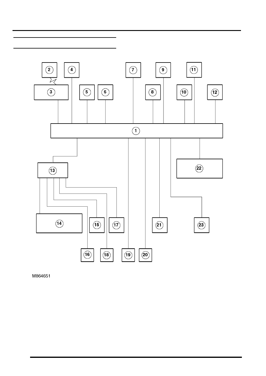
Alarm system block diagram
1 Body Control Unit (BCU)
2 Remote handset
3 Receiver
4 Fuel cut off switch
5 Ignition switch
6 Central door locking switch
7 Volumetric sensors
8 Bonnet activated alarm switch
9 Drivers door key lock/unlock switches
10 Door latch switches
11 Fuel flap release switch
12 Intelligent Driver Module (IDM)
13 Battery Backed Up Sounder (BBUS)
14 Alarm sounder
15 Vehicle horns
16 Direction indicators
17 Door lock actuators
18 Engine Control Module (ECM)
19 Starter motor
Нет комментариевНе стесняйтесь поделиться с нами вашим ценным мнением.
Текст