Discovery 2. Manual — part 360
NAVIGATION SYSTEM
DESCRIPTION AND OPERATION
87-15
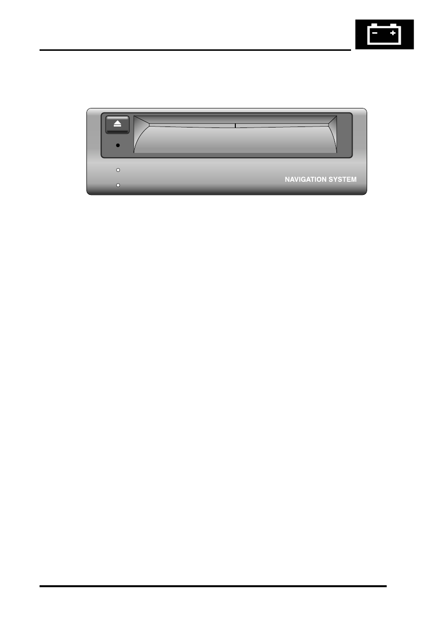
Navigation Computer
The Navigation computer is delivered pre-loaded with operating software, 2 languages and the Off Road navigation
software. The 2 pre-loaded languages are:
l
UK English (Female)
l
German (Male)
Software loading can be achieved at any time by inserting a software CD into the CD-ROM drive. The navigation
computer compares the version of software on the CD with that currently loaded. If the software version on the CD is
a later version it automatically loads the new software. The status of software loading is shown on the display unit.
On completion of software loading, the CD is automatically ejected. The user is prompted to remove the CD and
confirm. The computer then resets and restarts with the new software.
M86 6061
ON
CD-IN
NAVIGATION SYSTEM
87-16
DESCRIPTION AND OPERATION
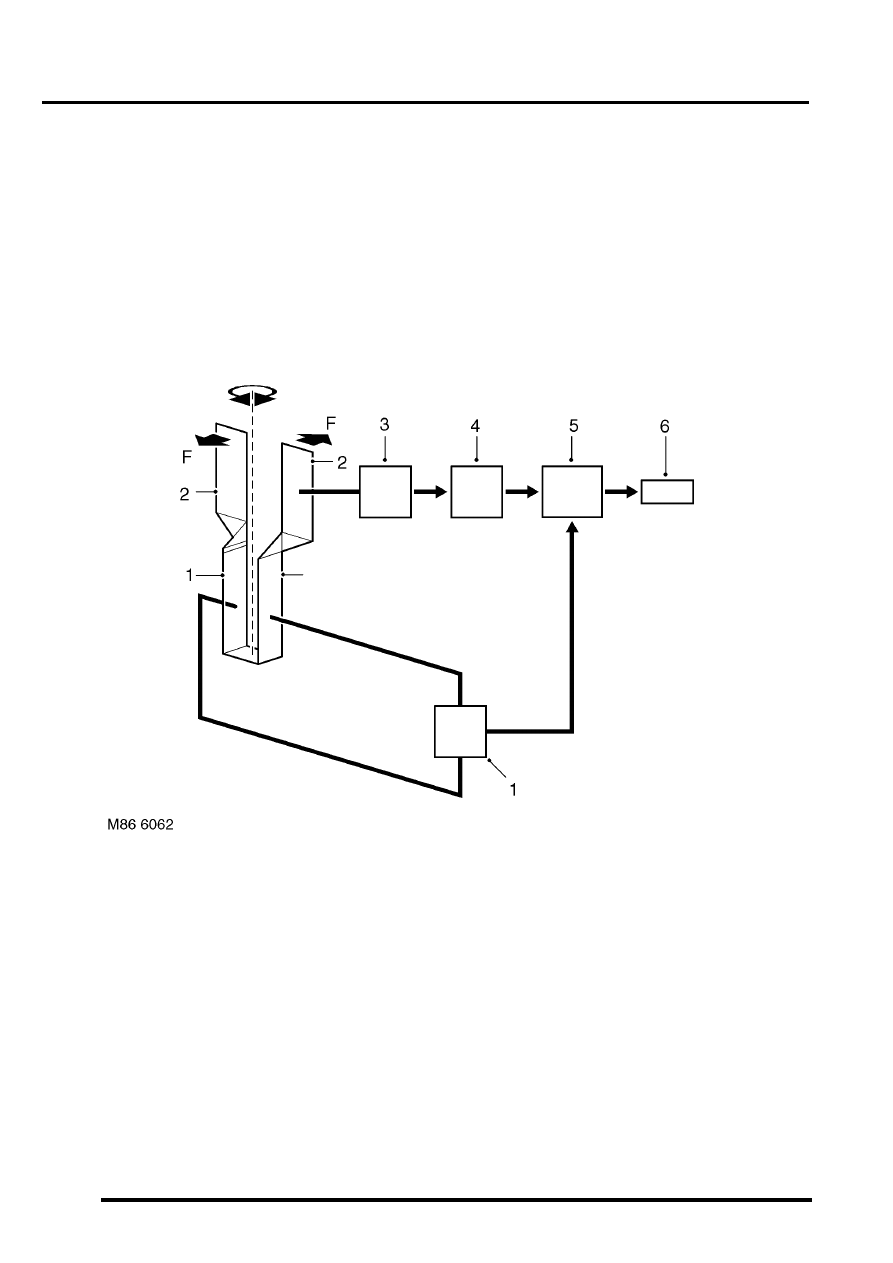
Piezo Gyro Sensor
1 Driver elements
2 Retaining element
3 Amplifier
4 Phase detector
5 Frequency filter
6 Navigation computer
7 Driver stage
The piezo gyro measures the motion of the vehicle around its vertical axis using the Coriolis force. The Coriolis force
is a force which accelerates a body moving away from the rotational axis against the direction of rotation of that axis.
In operation, a mass inside the sensor is excited to a point where it begins to vibrate, similar to a tuning fork. The
vibrations travel perpendicular to the rotational axis and cause continuous potential charge of the mass in relation to
the rotational axis. The forces are measured and converted into a yaw rate to calculate direction.
The sensor is supplied with a current from a driver stage. The current induces vibrations in the driver elements and
retaining elements. As the vehicle turns a corner, the rotational motion is detected by the retaining elements due to
the Coriolis force, and a small electrical voltage is produced.
The voltage is passed to an amplifier and the amplified signal is then passed to a phase detector. The phase detector
establishes the direction of rotation and passes a signal to a frequency filter. Because the gyro sensor is subject to
vibrations produced by means other than cornering, the frequency filter analyses the signals and removes signals not
produced by cornering forces. The filtered signal is passed from the frequency filter to the navigation computer, which
uses it to calculate the direction of travel.

NAVIGATION SYSTEM
DESCRIPTION AND OPERATION
87-17
GPS Antenna
The GPS antenna is installed on the rear of the roof, on the vehicle centreline. A diplexer unit on the underside of the
GPS antenna amplifies the radio signals received from the GPS satellites and transmits them through a co-axial cable
to the navigation computer for processing.
Display Unit
The display unit is integrated into the front stowage pocket, above the rear view mirror. The display unit is a colour
Liquid Crystal Display (LCD) that shows the programming menus, route guidance and traffic information. The display
illumination level automatically dims for night time viewing when the exterior lights are switched on.
NAVIGATION SYSTEM
87-18
DESCRIPTION AND OPERATION
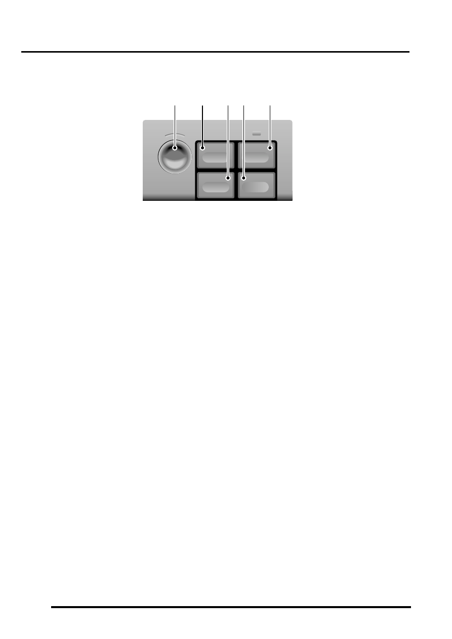
Switch Pack
1 Rotary controller
2 Menu switch
3 Repeat switch
4 Re-route switch
5 Mute switch
The switch pack is installed near the centre of the fascia, below the fascia panel switches. The switch pack contains
the switches for controlling the operation of the navigation system. The switches have the following functions:
Rotary Controller
The rotary controller is a combined rotary and push switch which is used to make all selections when operating the
navigation system. Rotating the switch scrolls up and down a vertical menu, or across a horizontal menu. Pressing
and releasing the switch selects a highlighted item.
Menu Switch
The menu switch is used to activate the system and, when the system is active, return the display to the main menu.
The menu switch is also used to activate and de-activate Trafficmaster.
Mute Switch
Pressing and releasing the mute switches toggles the audio instructions on and off. An orange LED in the switch
illuminates when the mute function is engaged.
Re-route Switch
During road navigation, pressing and releasing the re-route switch produces a menu on the display unit that allows
the driver to select a diversion from the current route of between 0 and 6 miles. Once the deviation distance is
selected, the navigation ECU plots the new route and issues the necessary instructions for the diversion.
Repeat Switch
Pressing and releasing the repeat key causes the navigation ECU to repeat the last audio instruction. The instruction
is only repeated if it is still valid.
Navigation Speaker
The navigation speaker is installed on the back of the lower closing panel on the driver's side of the fascia. The
speaker outputs the audio instructions for route guidance.
M86 6063
1
MUTE
RE-RTE
REPEAT
MENU
2
3
4
5
Нет комментариевНе стесняйтесь поделиться с нами вашим ценным мнением.
Текст