Discovery 2. Manual — part 598
STEERING
REPAIRS
57-41
Refit
1. Position PAS pump to auxiliary housing and
locate housing to engine. Fit and tighten
auxiliary housing bolts to 40 Nm (30 lbf.ft).
2. Tighten auxiliary housing nut to 10 Nm (7 lbf.ft).
3. Fit bolts securing PAS pump and tighten to 22
Nm (16 lbf.ft).
4. Position PAS pump pipe bracket, fit and tighten
bolt to 22 Nm (16 lbf.ft).
5. Fit and tighten PAS pump pressure pipe.
6. Fit PAS pump inlet hose and secure with clip.
7. Position jockey pulley and tighten bolt to 50 Nm
(37 lbf.ft).
8. Clean PAS pump pulley mating faces.
9. Position PAS pump pulley, fit bolts and tighten
to 22 Nm (16 lbf.ft).
10. Models with ACE: Clean ACE pump dowels
and dowel holes. Position ACE pump, fit bolts
and tighten to 25 Nm (18 lbf.ft).
11. Models with A/C: Clean A/C compressor
dowels and dowel holes. Position A/C
compressor, fit bolts and tighten to 22 Nm (16
lbf.ft).
12. Position air intake hose and secure with clips.
13. Secure harness to air intake hose with new
cable tie.
14. Fit auxiliary drive belt.
REPAIRS, Belt - auxiliary drive..
15. Bleed PAS system.
Pump - power steering - diesel
$% 57.20.14
Remove
1. Remove auxiliary drive belt.
REPAIRS, Belt - auxiliary drive.
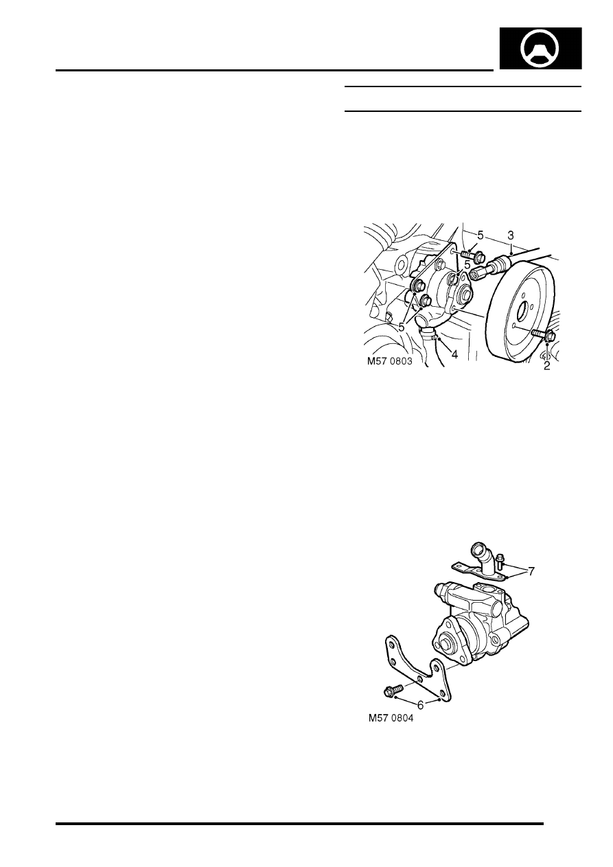
2. Remove 3 bolts securing PAS pump pulley and
remove pulley.
3. Position tray to catch spillage, release PAS
pump pressure pipe.
4. Remove clip and release PAS pump inlet hose.
CAUTION: Always fit plugs to open
connections to prevent contamination.
5. Remove 4 bolts and remove PAS pump.
6. Remove bolt, and remove mounting bracket
from PAS pump.
7. Remove 2 bolts, remove low pressure adaptor
pipe and discard 'O' ring.
STEERING
57-42
REPAIRS
Refit
1. Clean PAS pump and adaptor pipe.
2. Fit new 'O' ring to adaptor pipe, fit pipe and
tighten bolts to 10 Nm (7 lbf.ft).
3. Position mounting bracket to PAS pump, fit but
do not tighten bolt.
4. Position PAS pump and align pump drive to
coolant pump. Fit and tighten bolts to 25 Nm
(18 lbf.ft).
5. Tighten mounting plate bolt to 25 Nm (18 lbf.ft).
6. Clean PAS pump and pipe union.
7. Fit and tighten PAS pump pressure pipe to 20
Nm (15 lbf.ft).
8. Fit PAS pump inlet hose and secure with clip.
9. Clean PAS pump and pulley mating faces.
10. Position PAS pump pulley, fit and tighten bolts
to 10 Nm (7 lbf.ft).
11. Fit auxiliary drive belt.
REPAIRS, Belt - auxiliary drive.
12. Bleed power steering system.
Steering column assembly and lock
$% 57.40.01
Remove
1. Remove steering column intermediate shaft.
intermediate and universal joint - steering
column.
2. Remove rotary coupler.
3. Open fascia lower access panel.
4. Remove steering column nacelle.
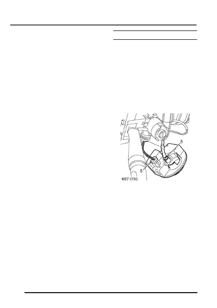
5. Disconnect multiplug and illumination bulb
from passive coil and remove passive coil.
STEERING
REPAIRS
57-43
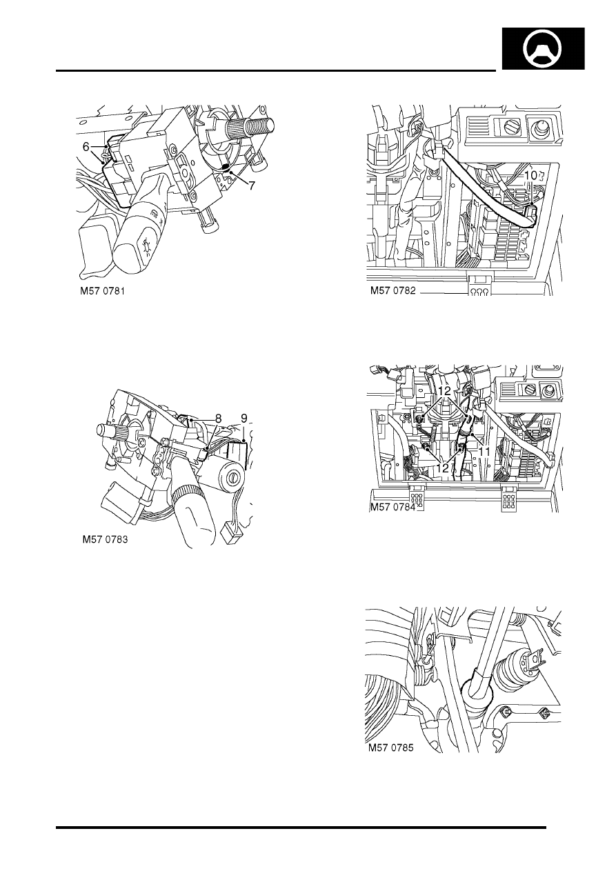
6. Disconnect 2 multiplugs from wiper switch
assembly.
7. Disconnect 2 multiplugs from light switch
assembly.
8. Loosen screw and remove switch assembly.
9. Disconnect ignition switch multiplug.
10. Disconnect multiplug from ignition switch
housing.
11. Release harness from column clip.
12. Remove 4 nuts securing steering column
assembly to fascia rail and remove steering
column assembly.
13. Remove rubber boot from steering column
assembly.
STEERING
57-44
REPAIRS
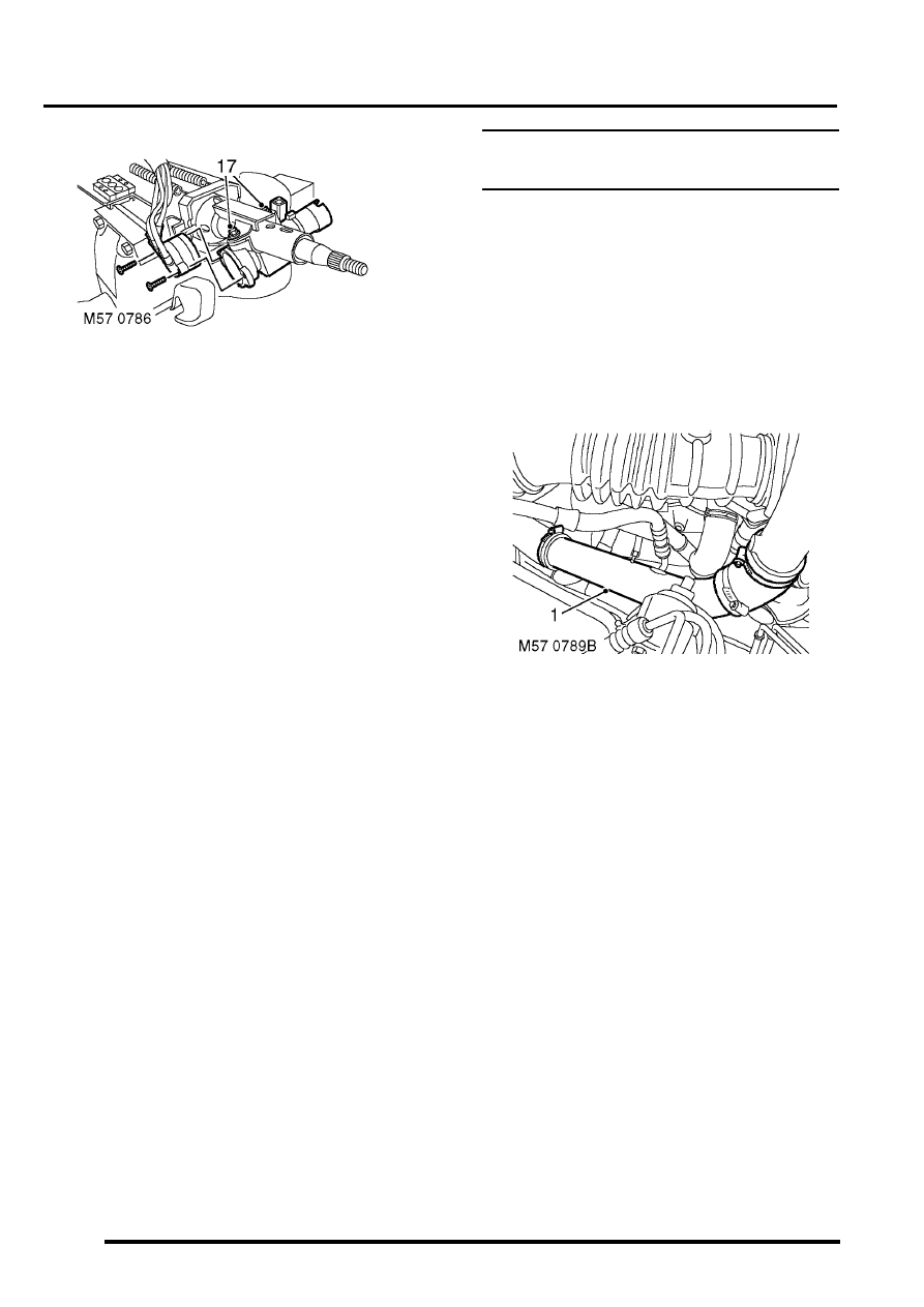
14. Position steering column assembly in a vice.
15. Remove 2 screws and remove ignition switch.
16. Remove cable tie and remove multiplug from
ignition switch.
17. Centre punch or drill out steering lock shear
bolts.
18. Remove steering lock
Refit
1. Position lock to steering column assembly and
fit shear bolts. Do not tighten shear bolts at this
stage.
2. Insert starter key, check operation of steering
lock and that key turns freely.
3. Tighten shear bolts fully and shear heads off.
4. Position ignition switch to column, fit and
tighten screws.
5. Position multiplug to switch and secure with
new cable tie.
6. Fit rubber boot to column.
7. Remove column from vice.
8. Position steering to fascia rail fit nuts and
tighten to 22 Nm (16 lbf.ft).
9. Secure harness to column clip.
10. Position rubber grommet.
11. Close access panel and secure turn buckles.
12. Connect ignition switch multiplugs.
13. Position column switch and tighten clamp
screw.
14. Connect column switch multiplugs.
15. Position passive coil, connect multiplug and
illumination bulb.
16. Fit steering column nacelle.
17. Fit rotary coupler.
18. Close fascia lower access panel.
19. Fit steering column intermediate shaft.
intermediate and universal joint - steering
column.
Shaft - intermediate and universal joint -
steering column
$% 57.40.22
The intermediate shaft has a red indicator clip
fitted which must be inspected at service, and
after the vehicle has been subject to an impact.
If the clip is not present or is not fully seated
against the clamp plate, a new assembly must be
fitted.
Remove
1. LHD diesel: Loosen 2 clips securing
intercooler to turbocharger hose. Place hose
aside.
Нет комментариевНе стесняйтесь поделиться с нами вашим ценным мнением.
Текст