Discovery 2. Manual — part 159
PROPELLER SHAFTS
OVERHAUL
47-9
OVERHAUL
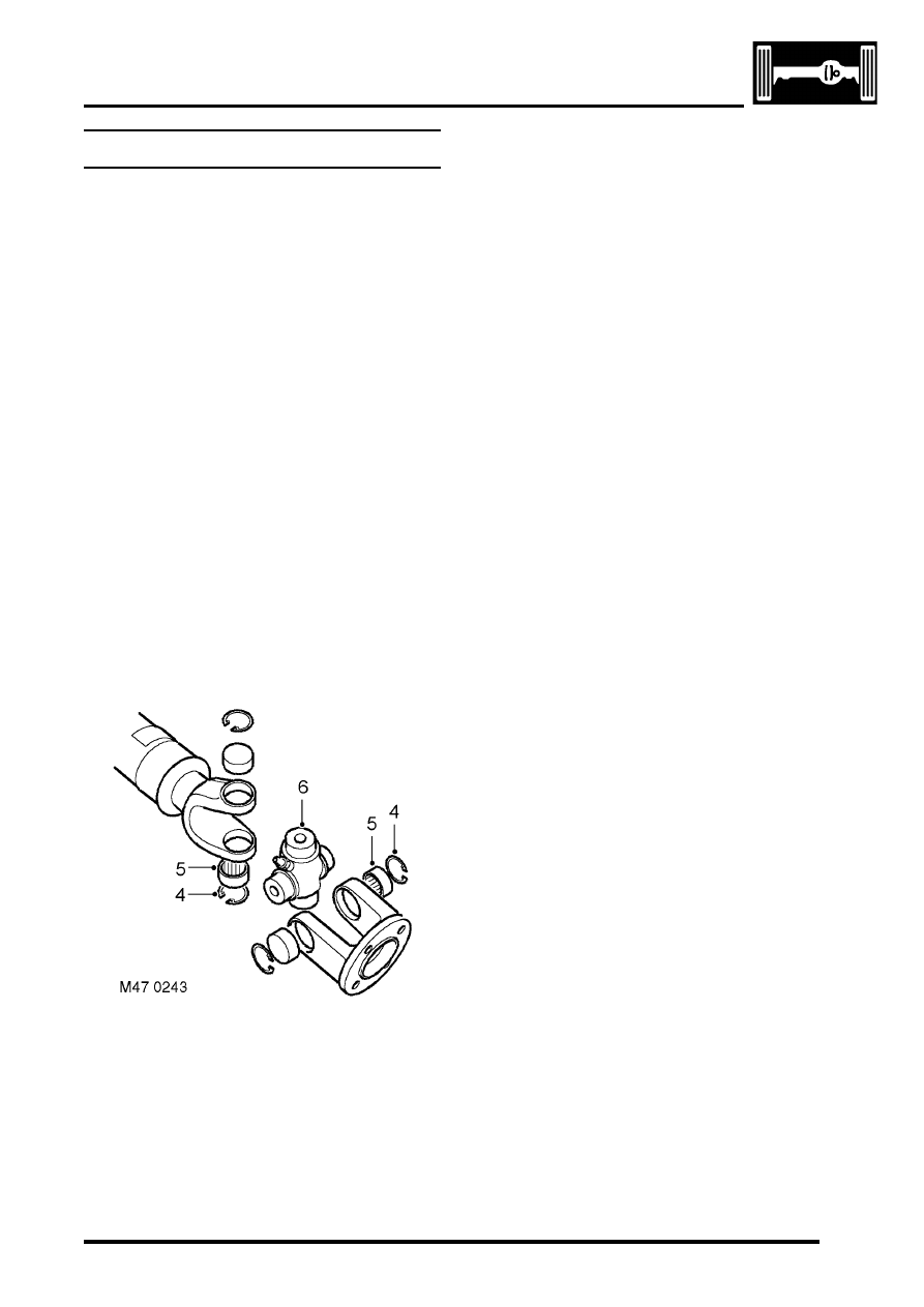
Propeller shaft
$% 47.15.11
The following bearing replacement procedure
applies to the universal joints of both the front and
rear propeller shafts, including the Hookes joint (i.e.
double universal joint) of the front propeller shaft.
Disassembly
1. Remove propeller shaft:
l
For front propeller shaft.
l
2. Thoroughly examine the universal joint for
signs of damage or wear.
3. Clean the universal joint bearing cups and
circlips.
CAUTION: Before removal, mark the
position of the spider pin relative to the
journal yoke ears on the propeller shaft
joint. This will ensure correct assembly and
reduce the possibility of imbalance.
4. Remove the circlips.
5. Tap the yokes to eject bearing cups. Remove
bearing cups.
6. Remove spider from yokes.
7. Clean yokes and bearing cup locations.
Reassembly
1. Remove bearing cups from new spider.
2. Check all needle rollers are present and
correctly positioned in bearing cups.
3. Enter new spider, with seals, into one of the
yokes.
4. Partially insert one bearing cup into yoke and
enter spider trunnion into bearing cup.
5. Insert opposite bearing cup in yoke.
6. Press both cups into place.
7. Press each cup into its respective location in
yoke up to lower land of circlip groove. Damage
may be caused to cups and seals if cups
pass this point.
8. Fit circlips and check no end float exists.
9. Engage spider in second yoke. Fit bearing cups
and circlips as described in steps 4 to 8.
10. Fit propeller shaft:
l
l
REAR AXLE
DESCRIPTION AND OPERATION
51-1
REAR AXLE
DESCRIPTION AND OPERATION
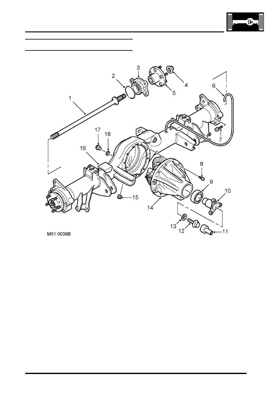
Rear axle component layout
1 Drive shaft
2 'O' ring
3 Hub bearing
4 Stake nut
5 Hub flange
6 Breather tube
7 Bolt
8 Bolt
9 Oil seal
10 Pinion flange
11 Centralising peg
12 Bolt
13 Washer
14 Differential unit
15 Drain plug
16 Axle casing
17 Oil level plug
18 'O' ring
REAR AXLE
51-2
DESCRIPTION AND OPERATION
Description
General
The rear axle consists of an axle casing with a differential unit attached to the right of the vehicle centre line. A wheel
hub is installed in each end of the axle casing and connected to the differential unit by a drive shaft.
Axle casing
The axle casing is of welded construction, with brackets on the casing exterior for attachment to the rear suspension.
A differential cover on the rear of the axle casing contains an oil level plug for checking and replenishment of the
differential unit lubricating oil. A magnetic drain plug is installed on the underside of the axle casing.
The interior of the axle casing is ventilated through a breather tube inserted in a red plastic sleeve in the top of the
casing. The open end of the breather tube is located between the chassis and the left rear wheelarch.
Differential unit
The differential unit is of the spiral bevel type, lubricated by splash oil. The unit consists of a differential carrier
attached to a pinion housing. In the pinion housing, the pinion is splined to a pinion flange which is secured with a bolt
and washer. An oil seal prevents leakage past the pinion flange.
Centralising peg
The centralising peg is a press fit in the centre of the pinion flange and provides a positive location for the rear
propellor shaft to ensure it is centralised with the flange.
Нет комментариевНе стесняйтесь поделиться с нами вашим ценным мнением.
Текст