Discovery 2. Manual — part 589

STEERING
DESCRIPTION AND OPERATION
57-5
Description
General
The major steering components comprise an impact absorbing telescopic steering column, a Power Assisted Steering
(PAS) box, a PAS pump, and fluid reservoir. Hydraulic fluid from the fluid reservoir is filtered and then supplied
through the suction line to the inlet on the PAS pump. The PAS pump supplies fluid to the steering box through a
pressure line routed above the front cross member. Fluid returns to the reservoir along the same route through a
return line. On LH drive vehicles the pipe route above the front cross member is still used, the length of pipe acting
as an oil cooler.
To minimise driver's injury in the event of an accident the steering system has a number of safety features including
a collapsible steering column. An additional safety feature is an air bag located in the steering wheel.
RESTRAINT SYSTEMS, DESCRIPTION AND OPERATION, Description - SRS.
Steering column assembly and intermediate shaft
The steering column central shaft comprises of two shafts, the upper shaft is splined to accept the steering wheel and
located in bearings in the column tube. A universal joint is located on the bottom of the upper shaft, the joint allows
for angular movement between the upper and lower shafts. The lower shaft is made in two parts, the top section of
the lower shaft is located outside of the lower section. The two sections of the lower shaft are connected by two nylon
injection moulded shear pins. The lower shaft goes through a lower bearing attached to the bulkhead, the lower shaft
is connected by a universal joint to the intermediate shaft in the engine compartment.
Steering column
An upper column tube provides for the location of the steering lock and ignition switch and also the steering switch
gear and a rotary coupler. The rotary coupler provides the electrical connection for the steering wheel mounted airbag,
switches and horn. The upper mounting bracket has two slots, a slotted metal bracket is held in each slot by four resin
shear pins.
The column is mounted on four captive studs which are located on a column mounting bracket. The captive studs
pass through the metal brackets, locknuts secure the steering column to the bulkhead. The two lower mountings are
fixed and cannot move when loads are applied to them. The upper mounting is designed to disengage or deform when
a load is applied, allowing the column to collapse in the event of an accident. The steering column must be replaced
as a complete assembly if necessary.
When an axial load is applied to the upper column tube, energy absorption is achieved by the following mechanism:
l
the mounting bracket deforms,
l
the resin shear pins holding the slotted metal brackets shear,
l
the top mounting bracket slides out of the slotted metal brackets.
The slotted metal brackets remain on the captive studs on the bulkhead. If the column mounting moves, injection
moulded shear pins retaining the two sections of the lower column shaft will shear. This allows the two sections of the
lower shaft to 'telescope' together.
In the event of a collision where the steering box itself moves, two universal joints in the column allow the intermediate
shaft to articulate, minimising movement of the column towards the driver. If movement continues energy absorption
is achieved by the following mechanism:
l
the decouple joint in the intermediate shaft will disengage,
l
the lower section of the steering column shaft will move through the lower bearing,
l
the injection moulded shear pins retaining the two sections of the lower column shaft will shear.
This allows the two sections of the lower shaft to 'telescope' together reducing further column intrusion. Protection to
the drivers face and upper torso is provided by an SRS airbag module located in the centre of the steering wheel.
RESTRAINT SYSTEMS, DESCRIPTION AND OPERATION, Description - SRS.
STEERING
57-6
DESCRIPTION AND OPERATION
Tilt adjustment
The column tilt adjuster lever mechanism is located on the LH side of the steering column and allows the upper column
tube, nacelle and steering wheel assemblies to be tilted up or down a maximum of 7.5
°
or 47 mm (NAS vehicles have
a smaller range of movement than the ROW vehicles).
The pawl of the mechanism is attached to the lower column and is allowed to pivot, a toothed quadrant is fixed to the
upper column tube.
When the lever on the LH side of the steering column is raised the mechanism releases the pawl from the toothed
quadrant, this allows the column to be moved. When the lever is released two return springs pull the pawl into
engagement with the toothed quadrant.
Steering column lock (All except NAS)
The steering column lock houses the ignition switch, ignition illumination light ring, key lock barrel and the alarm
passive coil. The steering lock is attached to the upper column with two shear bolts. The bolts are tightened to a
torque which shears off the heads of the bolts preventing easy removal of the steering lock.
The steering lock operates by a bolt, which emerges when the ignition key is turned to position 'O' and the ignition key
removed. The bolt engages in a lock collar located on the upper shaft in the upper column tube. The lock collar is
attached to the upper shaft by a 'wave form' interference ring. If a high torque is applied via the steering wheel with
the lock engaged, the lock collar will slip on the upper shaft. This prevents damage to the steering lock, yet still
prevents the vehicle from being driven.
Steering column lock (NAS only)
The steering column lock houses the ignition switch, ignition illumination light ring, key lock barrel and the alarm
passive coil. The steering lock is attached to the upper column with two shear bolts. The bolts are tightened to a
torque which shears off the heads of the bolts preventing easy removal of the steering lock.
The steering column lock operates by a bolt, which emerges when the ignition key is turned to position 'O' and the
ignition key removed. The bolt engages in a groove machined into the upper shaft in the column tube.
Steering wheel
The steering wheel comprises a cast centre and wire frame onto which the soft polyurethane foam is moulded. The
steering wheel is located on the upper column shaft by a spline and is secured with a nut. A remote radio control switch
(if fitted) is located on the LH side of the steering wheel, a cruise control switch may be located on the RH side. Horn
switches are located on each side of the centre of the steering wheel and protrude through the airbag module cover.
Both switches are connected by wires to the rotary coupler connector.
Intermediate shaft
One end of the intermediate shaft is attached to the steering column lower shaft by a splined universal joint and a bolt,
the universal joint is part of a rubber coupling assembly. The rubber coupling assembly is covered by a heat shield
and connects to the lower section of the intermediate shaft via a decouple joint. The rubber coupling reduces the
shocks felt by the driver through the steering wheel. A second universal joint on the other end of the intermediate shaft
is held in by a bolt. The universal joint is splined and engages with the splined rotor (input) shaft of the steering box.
The decouple joint consists of a metal plate that has open ended slots, the plate is bolted through the slots into the
other half of the decouple joint. The top half of the decouple joint has a slot that accepts the lower section of the
intermediate shaft. The slotted metal plate clamps the lower section of the intermediate shaft to the top section. An
indicator clip is installed between the slotted metal plate and the top half of the decouple joint.
If the intermediate shaft is compressed in an accident, the slotted metal plate in the decouple joint will disengage if
sufficient force is applied to the front end of the shaft. If the forces involved do not disengage the shaft, the red
indicator clip located in the decouple joint will break off if the shaft moves. The intermediate shaft cannot be repaired
and must be replaced as an assembly if accident damage occurs.
STEERING
DESCRIPTION AND OPERATION
57-7
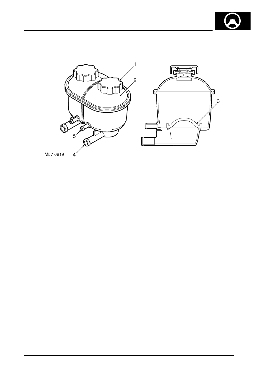
Reservoir
1 Filler cap
2 Reservoir body (dual PAS/ACE shown )
3 Filter
4 Supply connection
5 Return connection
The fluid reservoir is made of moulded plastic and is located on LH side of the engine compartment, on a bracket
which is attached to the inner wing. Dependent on the vehicles specification the reservoir may be a dual PAS/ACE,
or PAS only reservoir. Both types of reservoir are similar to each other the dual PAS/ACE reservoir has two chambers,
the PAS only reservoir has one chamber of a larger capacity. On both types of reservoir the PAS chamber has its own
filler cap and is identified by lettering on the reservoir body.
A filter of fine polyester mesh is moulded into the base of the chamber. The filter removes particulate matter from the
fluid before it is drawn into the supply connection and is non-serviceable. Upper and lower level marks are moulded
into the reservoir body, the reservoir is fitted with filler cap, a seal in the cap prevents leakage. The filler cap is pushed
onto a latch and turned through 90
°
to lock. A breather hole is incorporated in the cap to allow venting of air due to
fluid level changes during operation. The breather hole also allows air that may be in the fluid to separate out and vent
to atmosphere.
The reservoir holds hydraulic fluid and allows for expansion and contraction of the fluid due to temperature variations.
With the reservoir correctly filled the inlet to the PAS pump will be kept covered at normal operational attitudes. The
fluid flowing to the reservoir is cooled by convection from the pipe surfaces, the fluid held in the reservoir also allows
convection from the sides of the reservoir to take place. The total capacity of the reservoir with PAS only is 1000 cc
(0.264 US gallons), for vehicles fitted with PAS and ACE the total capacity of the reservoir is 500 cc (0.132 US
gallons).
STEERING
57-8
DESCRIPTION AND OPERATION
Steering box
The steering box is located behind the first cross member of the chassis and is secured to the chassis rail with four
bolts. The steering box is of the worm and roller type and has a rotary control valve. The steering box is connected to
the steering knuckles of the front road wheels by the drop arm, drag link and track rod. The steering box is lubricated
by the hydraulic fluid in the housing. The input shaft is attached to the steering wheel via the intermediate shaft and
steering column. The drop arm is secured to the output shaft with a nut and tab washer. A ball joint allows movement
between drop arm and drag link, the ball joint is secured with a locknut. The steering box requries approximately 3.5
turns from lock to lock.
As a maintenance aid, an alignment bolt can be used to lock the drop arm at the steering box centre position. The bolt
fits in a groove in the rear face of the drop arm and screws in to a threaded hole on the bottom of the steering box
housing.
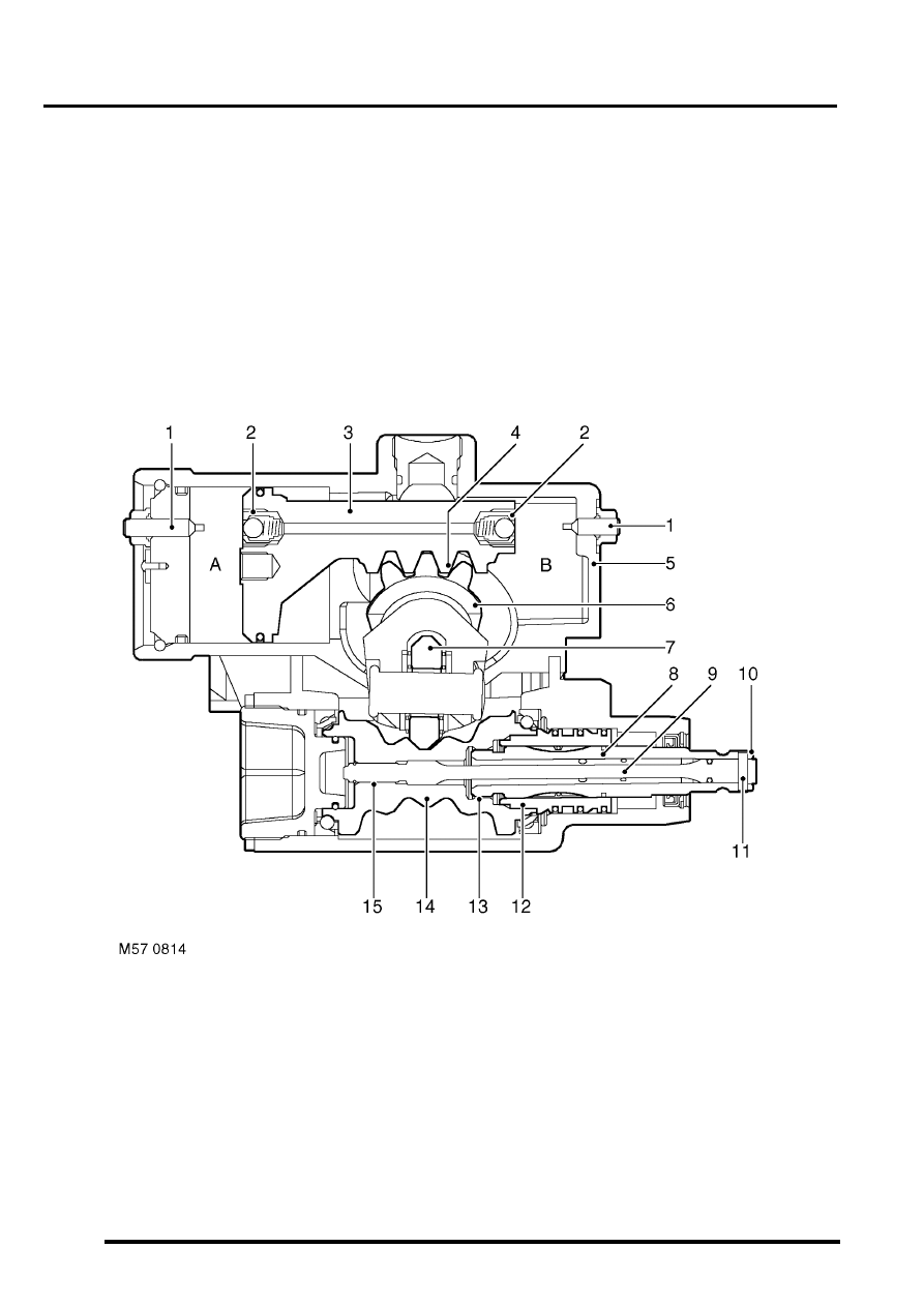
Cross section through steering box
1 Relief valve stop 2 off
2 Relief valve 2 off
3 Piston
4 Rack
5 Housing
6 Output shaft
7 Roller
8 Valve rotor
9 Torsion bar
10 Input shaft
11 Pin
12 Valve sleeve
13 Course spline
14 Worm gear
15 Spline (worm gear to torsion bar)
Нет комментариевНе стесняйтесь поделиться с нами вашим ценным мнением.
Текст