Discovery 2. Manual — part 734
BODY CONTROL UNIT
DESCRIPTION AND OPERATION
86-3-3
BCU outputs
The BCU processes the input signals it receives and uses the information to determine the control outputs that need
to be established for any given set of conditions. The BCU provides controlled outputs for the following systems:
l
Interior courtesy lamps.
l
Fuel flap release actuator.
l
Anti-theft status LED.
l
Engine Control Module.
l
Door lock actuators.
l
Direction indicators and hazard warning lamps.
l
Headlamps.
l
Alarm sounder.
l
Vehicle horns.
l
Battery backed sounder.
l
Starter relay.
l
Passive re-mobilisation exciter coil.
Simultaneous switching of outputs in different units is limited by the bus transfer time, but the skew is no longer than
100 ms for either the BCU or the IDM. When the processor is reset, all outputs are switched off until the inputs have
been read for the first time to check current condition.
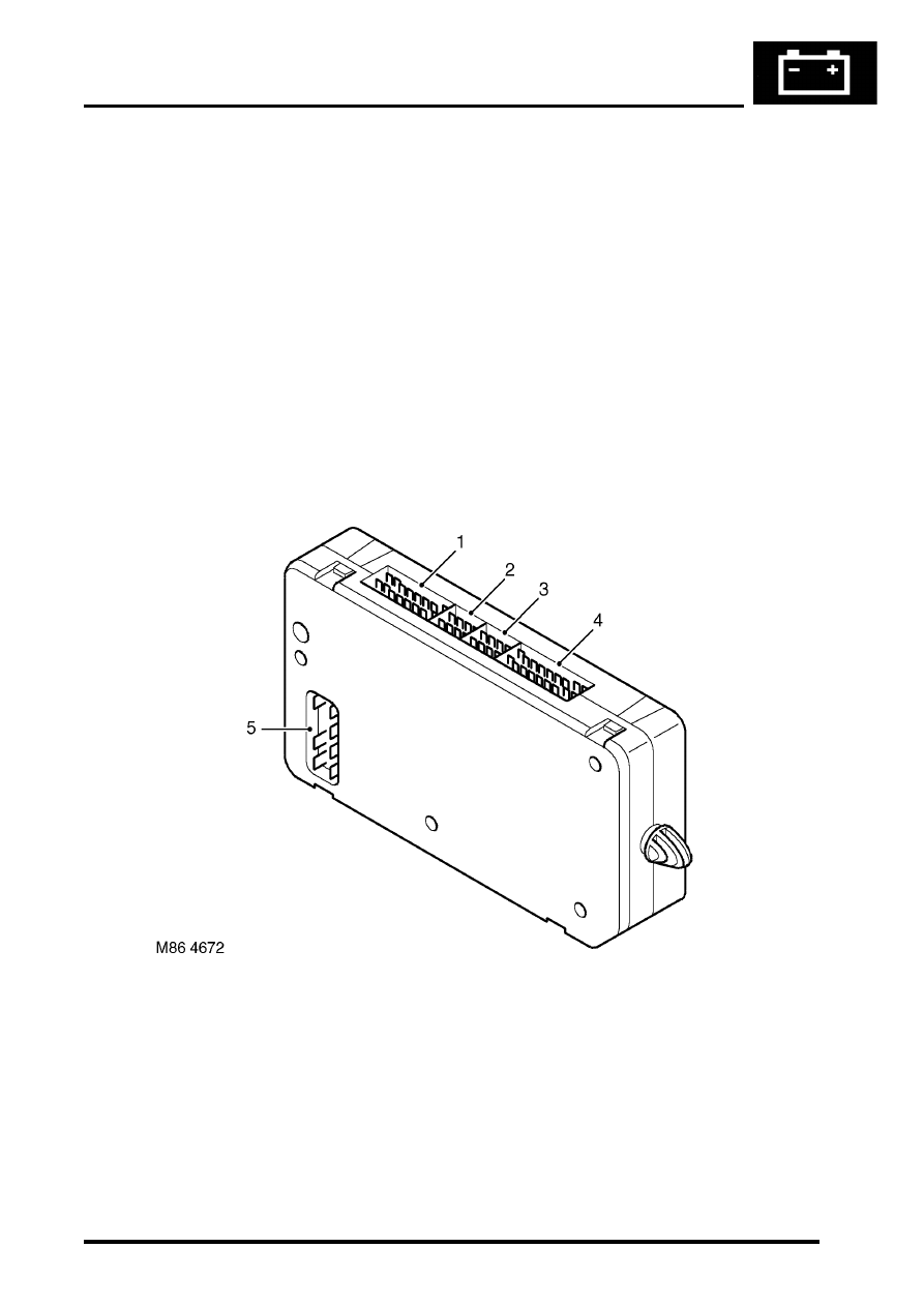
BCU to harness connectors
1 Connector C0661
2 Connector C0662
3 Connector C0663
4 Connector C0660
5 Connector C0664
BODY CONTROL UNIT
86-3-4
DESCRIPTION AND OPERATION
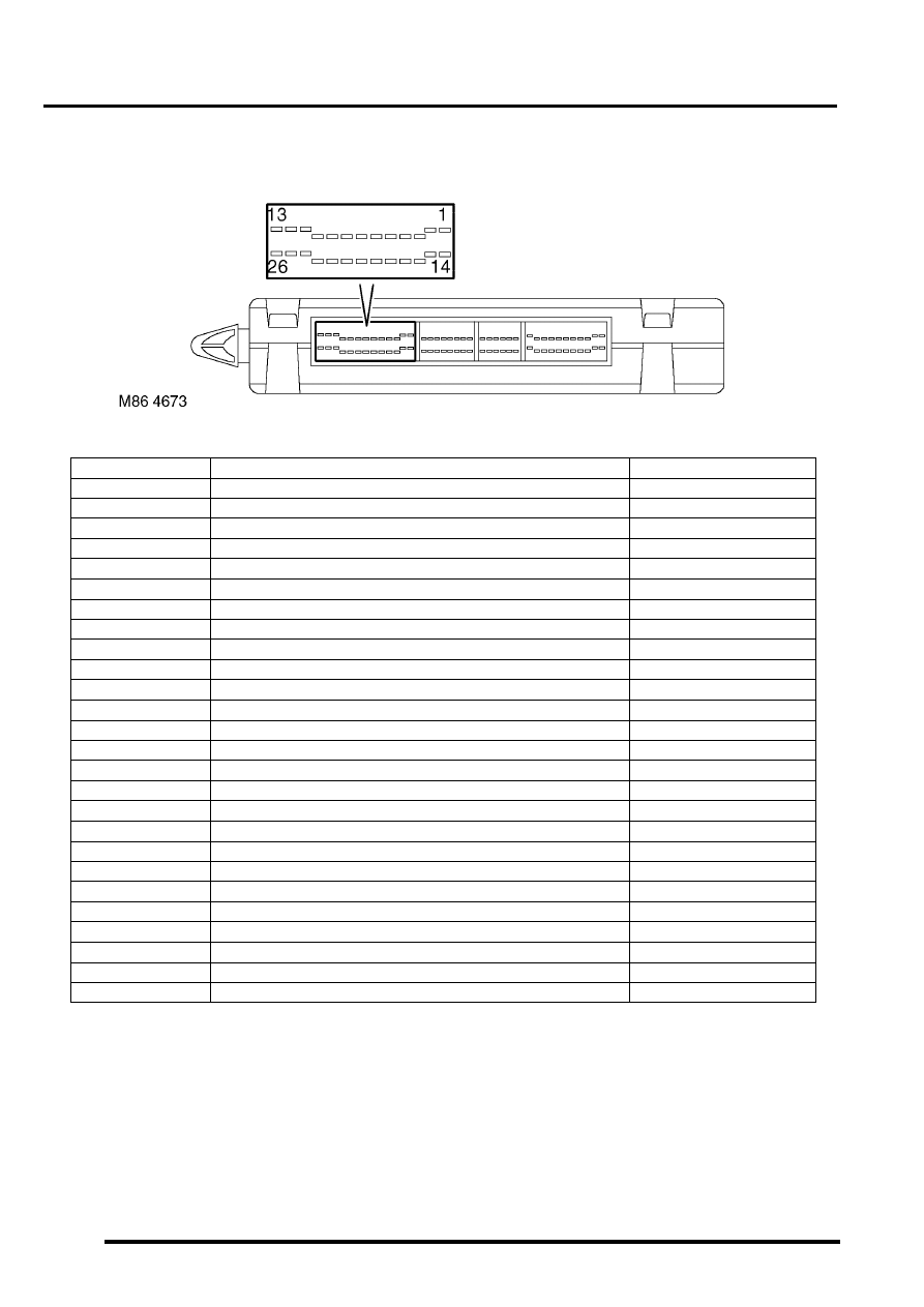
The pinout details for the BCU connectors are defined below:
C0660 connector pin details
Pin No.
Description
Input/Output
1
Ignition power supply
Input
2
Right front window - down
Input
3
Auxiliary power supply
Input
4
Passenger or rear door open
Input
5
Driver's door key lock
Input
6
RH indicator selected
Input
7
Front fog lamps selected
Input
8
Gear position feedback 'R'
Output
9
Gear position feedback 'P'
Output
10
SLS too high (audible warning)
Input
11
Earth
-
12
Vehicle raise/lower request
Output
13
Battery power supply
Input
14
Heated front screen selected
Input
15
Bonnet open
Input
16
CDL doors lock
Input
17
Driver's door open
Input
18
Left front window up
Input
19
Right front window up
Input
20
Rear washer pump
Input
21
Front intermittent wiper switch
Input
22
Gear position feedback '1'
Output
23
Gear position feedback '2'
Output
24
Gear position feedback '3'
Output
25
Gear position feedback 'D'
Output
26
Gear position feedback 'N'
Output
BODY CONTROL UNIT
DESCRIPTION AND OPERATION
86-3-5
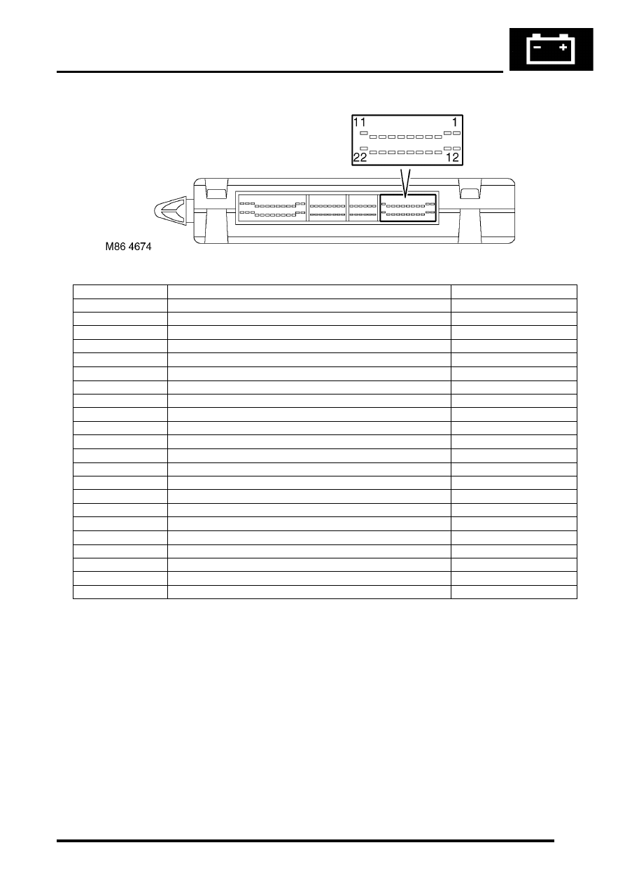
C0661 connector pin details
Pin No.
Description
Input/Output
1
Serial bus to instrument pack and IDM
Input/Output
2
Not used
-
3
Battery backed up sounder code (AL)
Output
4
Diagnostic bi-directional 'K'-line
Input/Output
5
RF regulated power supply
Output
6
RF receiver input
Input
7
Brake switch activated
Input
8
Reverse gear selected
Input
9
Sunroof enable line
Output
10
Robust immobilisation
Output
11
Front washer pump
Input
12
Heated front screen relay
Output
13
Heated front screen active
Output
14
Battery backed up sounder code (ST)
Output
15
Heated rear screen active
Output
16
'N' or 'R' or 'P' or brake selected
Output
17
Not used
-
18
Passive remobilisation exciter coil
Output
19
RF battery supply from fuse 20 in passenger compartment fusebox
Input
20
Security status LED
Output
21
Front intermittent wiper
Input
22
Driver's door key unlock
Input
BODY CONTROL UNIT
86-3-6
DESCRIPTION AND OPERATION
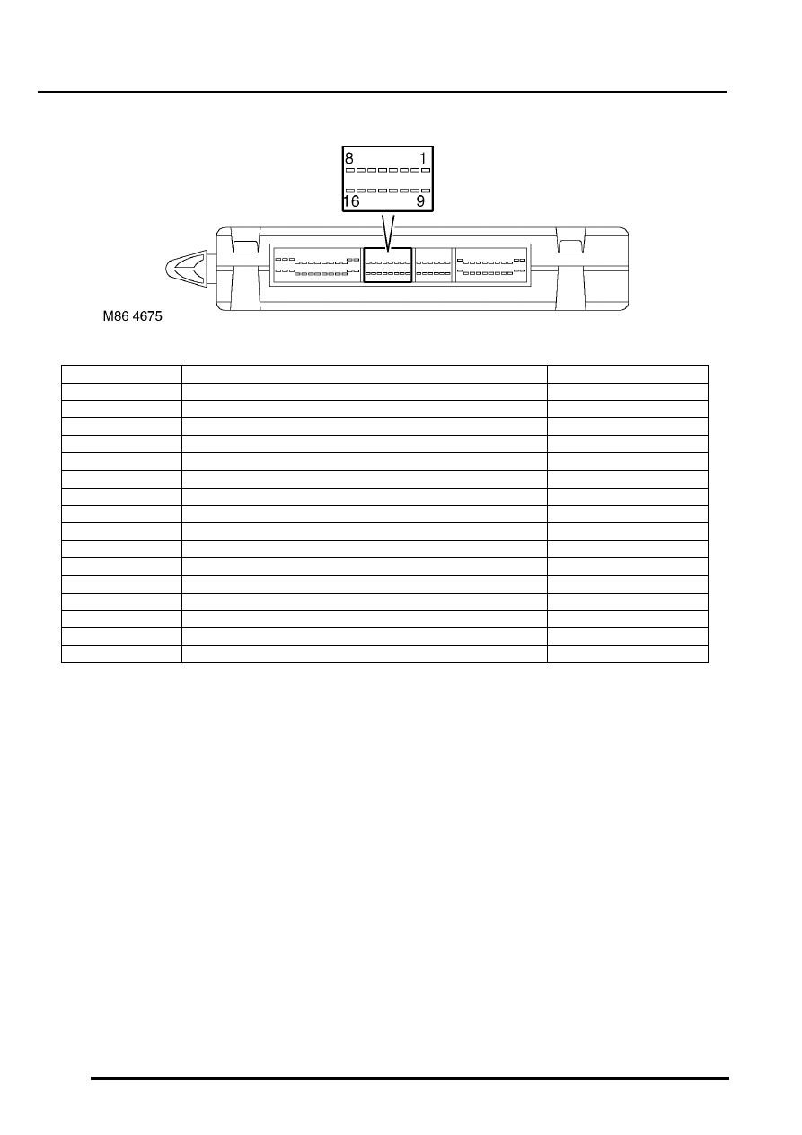
C0662 connector pin details
Pin No.
Description
Input/Output
1
Front left window - down
Input
2
Ignition key inserted
Input
3
Rear wiper
Input
4
Vehicle horns
Input
5
Crank enable
Output
6
Gear position switch (Y contacts)
Input
7
CDL doors unlock
Input
8
Rear fog lamps selected
Input
9
Gear position switch (W contacts)
Input
10
Drive selected (HDC)
Output
11
Ignition key interlock solenoid
Output
12
Headlamp powerwash
Output
13
Gear position switch (X contacts)
Input
14
Not used
-
15
Transfer box - neutral selected
Input
16
Seat buckle fastened
Input
Нет комментариевНе стесняйтесь поделиться с нами вашим ценным мнением.
Текст