Discovery 2. Manual — part 451
EMISSION CONTROL - V8
DESCRIPTION AND OPERATION
17-2-3
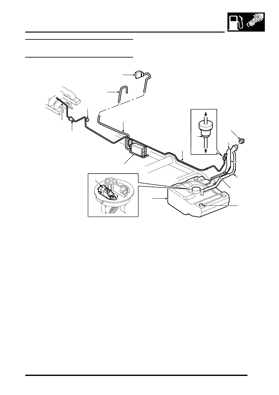
Evaporative emission system
component layout
1 Purge valve
2 Service port
3 Snorkel tube (UK / ROW only)
4 CVS unit (NAS vehicles with vacuum type leak
detection only)
5 EVAP canister breather tube
6 Vent pipe – fuel tank to EVAP canister
7 Relief valve regulated flow
8 Relief valve (UK / ROW only)
9 Relief valve free flow
10 Fuel filler cap
11 Liquid vapour separator (UK / ROW type
shown)
12 Fuel filler hose (UK / ROW type shown)
13 Tank breather hose (UK / ROW only)
14 Vent hose
15 Roll over valves (ROV's) – (4 off, UK / ROW
spec. shown)
16 Fuel tank and breather assembly
17 EVAP canister
18 Purge line connection to engine manifold
19 Tank EVAP system pressure sensor (NAS
vehicles with vacuum type leak detection only)
M17 0209
4
3
1
6
5
16
10
8
13
17
9
7
11
12
15
14
18
2
19
EMISSION CONTROL - V8
17-2-4
DESCRIPTION AND OPERATION
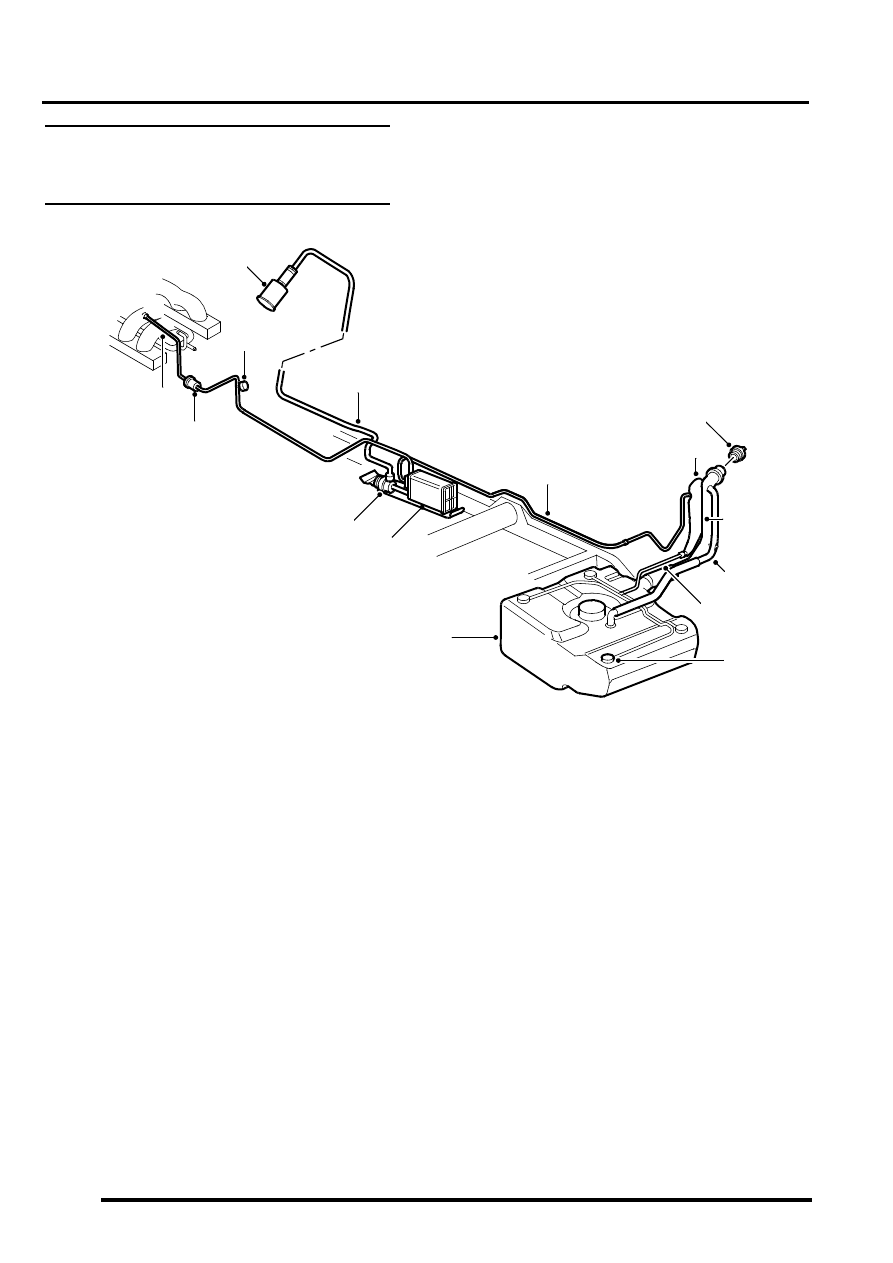
Evaporative emission system (with
positive pressure leak detection)
component layout (NAS only)
1 Purge valve
2 Service port
3 Air filter canister
4 EVAP canister breather tube
5 Leak detection pump
6 EVAP canister
7 Vent pipe – fuel tank to EVAP canister
8 Liquid vapour separator (metal)
9 Fuel filler cap
10 Fuel filler
11 Fuel tank breather assembly
12 Vent hose
13 Roll over valves (inside fuel tank)
14 Fuel tank
15 Purge line connection to engine manifold
M17 0208
3
1
7
4
14
11
6
8
10
13
12
15
2
5
9
EMISSION CONTROL - V8
DESCRIPTION AND OPERATION
17-2-5
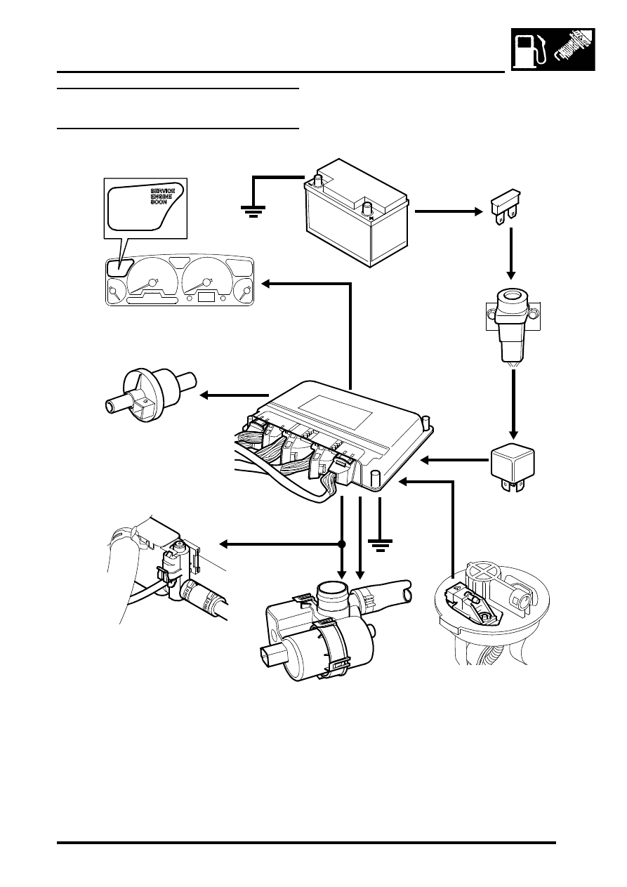
Evaporative emission system control
diagram
1 Battery
2 Fuse 13 (engine compartment fusebox)
3 Inertia switch
4 Main relay (engine compartment fusebox)
5 Engine Control Module (ECM)
6 Purge Valve (black harness connector)
7 Canister vent solenoid (CVS) valve – NAS
vehicles with vacuum type EVAP system leak
detection capability only
8 Leak detection pump – NAS vehicles with
positive pressure type EVAP system leak
detection capability only
9 Fuel tank pressure sensor – NAS vehicles with
vacuum type EVAP system leak detection
capability only
10 Instrument pack (MIL warning light)
M17 0210
1
2
3
4
5
6
7
9
8
10
EMISSION CONTROL - V8
17-2-6
DESCRIPTION AND OPERATION
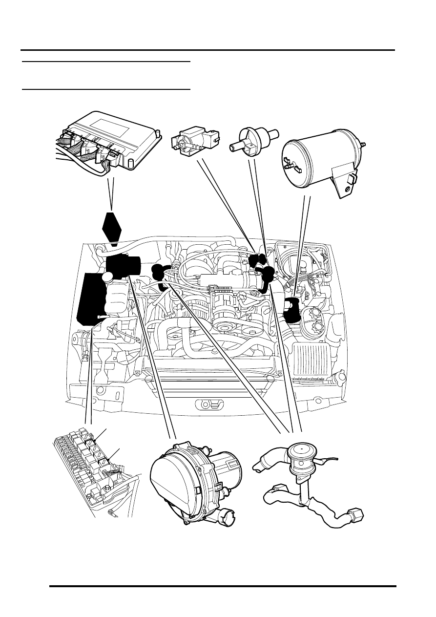
Secondary air injection system
component layout
M17 0206
1
2
3
4
5
6
8
7
Нет комментариевНе стесняйтесь поделиться с нами вашим ценным мнением.
Текст