Discovery 2. Manual — part 403

ENGINE - TD5
DESCRIPTION AND OPERATION
12-1-9
1 Acoustic cover
2 Oil filler flap
3 Rear acoustic cover
4 Rear acoustic cover inserts (2 off)
5 Rear acoustic cover grommets (2 off)
6 Rear acoustic cover screws (2 off)
7 Acoustic cover grommets (3 off)
8 Acoustic cover bolts (3 off)
9 Camshaft cover isolators (13 off)
10 Camshaft cover flange screws (13 off)
11 Breather hose clip
12 Breather hose
13 Breather hose to breather valve clip
14 Breather valve
15 Camshaft cover seal
16 Oil separator plate
17 Oil separator plate gasket
18 Camshaft cover
19 Acoustic cover to camshaft cover seal
20 Oil filler cap and seal
ENGINE - TD5
12-1-10 DESCRIPTION AND OPERATION
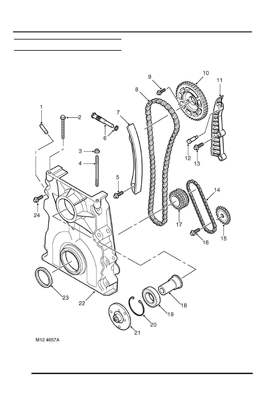
Camshaft timing chain components

ENGINE - TD5
DESCRIPTION AND OPERATION 12-1-11
1 Vacuum pump stub pipe
2 Cylinder head to timing chain cover bolt
3 Cylinder head to timing chain cover nut
4 Cylinder head to timing chain cover stud
5 Tensioner assembly pivot screw
6 Tensioner adjuster
7 Tensioner arm assembly
8 Duplex timing chain – crankshaft to camshaft
sprocket
9 Camshaft sprocket bolts (3 off)
10 Camshaft sprocket
11 Fixed chain guide
12 Fixed guide pin
13 Fixed chain guide to cylinder block screws
14 Oil pump drive chain
15 Oil pump sprocket
16 Oil pump sprocket screw
17 Crankshaft sprockets
18 Bearing to viscous fan shaft
19 Viscous fan to cover bearing
20 Circlip
21 Hub – viscous fan to bearing flange
22 Timing chain cover
23 Timing chain cover to crankshaft seal
24 Timing cover to cylinder head screws (8 off)
ENGINE - TD5
12-1-12 DESCRIPTION AND OPERATION
Description
General
The Td5 diesel engine is a 2.5 litre, 5 cylinder, in-line direct injection unit having 2 valves per cylinder, operated by a
single overhead camshaft. The engine emissions, on pre EU3 models, comply with ECD2 (European Commission
Directive) and on EU3 models, comply with ECD3 legislative requirements. Both models employ electronic engine
management control, positive crankcase ventilation and exhaust gas recirculation to limit the emission of pollutants.
The unit is water cooled and turbo-charged and is controlled by an electronic engine management system.
The engine is a monobloc cast iron construction with an aluminium stiffening plate fitted to the bottom of the cylinder
block to improve lower structure rigidity. The cylinder head and sump are cast aluminium. An acoustic cover is fitted
over the upper engine to reduce engine generated noise.
The engine utilises the following features:
l
Electronic Unit Injectors (EUI's) controlled by an Engine Management System for precise fuel delivery under
all prevailing operating conditions.
l
Turbocharging which delivers compressed air to the combustion chambers via an intercooler for improved
power output.
l
Fuel Cooler
l
Oil Cooler
l
Centrifuge Oil Filter
l
Hydraulic Lash Adjusters with independent finger followers
Cylinder block components
The cylinder block components are described below:
Cylinder Block
The cylinders and crankcase are contained in a single cast iron construction. The cylinders are direct bored and
plateau honed with lubrication oil supplied via lubrication jets for piston and gudgeon pin lubrication and cooling. It is
not possible to rebore the cylinder block if the cylinders become worn or damaged. Three metal core plugs are fitted
to the three centre cylinders on the right hand side of the cylinder block.
Lubrication oil is distributed throughout the block via the main oil gallery to critical moving parts through channels
bored in the block which divert oil to the main and big-end bearings via oil holes machined into the crankshaft. Oil is
also supplied from the cylinder block main gallery to the five lubrication jets which cool and lubricate the piston and
gudgeon pins. Plugs are used to seal both ends of the main oil gallery at front and rear of the engine block. An oil
cooler is fitted to the LH side of the engine block; ports in the oil cooler assembly mate with ports in the cylinder block
to facilitate coolant flow. Oil is diverted through the oil cooler, centrifuge filter and full-flow filter before supplying the
main oil gallery. A tapping in the oil filter housing provides a lubrication source for the turbocharger bearings and an
oil pressure switch is included in a tapping in the oil cooler housing which determines whether sufficient oil pressure
is available to provide engine lubrication and cooling.
Cylinder cooling is achieved by water circulating through chambers in the engine block casting. A threaded coolant
jacket plug is located at the front RH side of the cylinder block.
Cast mounting brackets are bolted to both sides of the engine block for mounting the engine to the chassis on the LH
and RH hydramount studs.
The gearbox bolts directly to the engine block; a gearbox shim plate is located between the adjoining faces of the
gearbox and the flywheel side of the engine block and is fixed to the rear of the engine block by two bolts. Two hollow
metal dowels locate the rear of the cylinder block to the gearbox shim plate. The gearbox casing provides the
mounting for the starter motor.
A port is included at the rear left hand side of the cylinder block which connects to the turbocharger oil drain pipe to
return lubrication oil to the sump.
A plug sealing the lubrication cross-drilling gallery is located at the front right hand side of the cylinder block and plugs
for the main lubrication gallery is included at the front and rear of the cylinder block.
Нет комментариевНе стесняйтесь поделиться с нами вашим ценным мнением.
Текст