Discovery 2. Manual — part 337

IN CAR ENTERTAINMENT
DESCRIPTION AND OPERATION
86-6-9
Inputs and outputs
The radio cassette player receives a mute signal from the telephone system if a call is received, when the call finishes
the mute is removed and the system resumes play. Inputs are also received from the steering wheel control system
(mid line and high line sytems). When the system is turned on, the high line systems radio cassette player:
l
sends a 'power on enable' to the power amplifier
l
sends an 'enable' signal to the radio headphone amplifiers.
On the high line system the radio cassette player also sends and receives signals from the CD-autochanger and rear
headphone amplifiers (if fitted). On high line systems the radio cassette player sends audio signals to the power
amplifier.
Remote radio steering wheel controls (midline and high line systems)
The remote radio control switch is located on the LH side of the steering wheel and is secured with two screws. The
wiring from the remote radio control switch plugs in to a connector that is part of the steering wheel rotary coupler.
Operation of the remote radio control switches allow the driver to control the ICE without releasing the steering wheel.
Volume, mode and selection functions can be carried out using the steering wheel mounted control switches. Control
inputs from the remote radio control switches are sent to the radio cassette player.
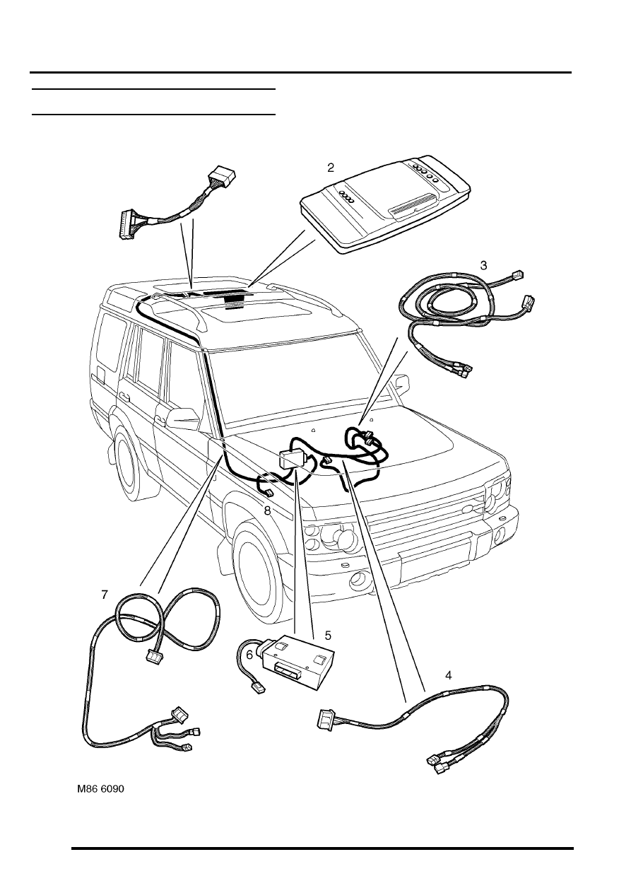
C0098
1
Telephone mute
Input
2
Steering wheel remote radio controls
Input
3
Steering wheel remote radio controls
Output
4
Permanent battery feed
Input
5
System enable
Output
6
Illumination
Input
7
Auxilary feed
Input
8
Earth
Input
C0921 (high line systems)
1
Radio headphone left channel
Output +
2
Radio headphone right channel
Output +
3
Telephone audio
Input +
4
Radio headphone left channel
Output -
5
Radio headphone right channel
Output -
6
Telephone audio
Input -
C0922 (high line systems)
7
Radio headphone active
Input
8
I-BUS communications
Input/Output
9
Audio amplifier spatial imaging enable
Output
10
Radio headphone LH remote control
Input
11
Radio headphone RH remote control
Input
12
Headphone remote controls feed
Output
C1354 (high line systems)
13
CD-autochanger audio left channel
Input +
14
CD-autochanger audio right channel
Input +
15
CD-autochanger audio earth
Output
16
CD-autochanger audio left channel
Input -
17
CD-autochanger audio right channel
Input -
18
Not Used
19
CD-autochanger I-BUS communications link
Input/Output
20
CD-autochanger permanent feed
Output
IN CAR ENTERTAINMENT
86-6-10 DESCRIPTION AND OPERATION
Aerial
On base and midline ICE systems an AM/FM aerial is built-in to the side window glass on the RH side of the vehicle.
An amplifier is located on the frame above the rear side widow behind the rear quarter trim, and is secured (and
earthed) with one bolt. Coaxial leads connect the aerial to the aerial amplifier and radio cassette. Power is supplied
from the auxilary relay in the engine compartment fuse box, through a fuse in the passenger compartment fusebox to
the amplifier.
On high line ICE systems two amplified aerials are built-in to the side window glass of the vehicle. The two aerials are
an AM/FM aerial on the RH side, and an FM aerial on the LH side. The amplifier for each aerial are located on the
frame above each rear side widow behind the rear quarter trim, and are each secured (and earthed) with one bolt.
Amplified aerials improve the reception quality, the FM aerial gives improved reception in areas of poor signal
(diversity) conditions in urban areas. A Power feed from the radio cassette player is connected to the amplified aerials,
power is available when the cassette player is operating. The aerials are connected to the radio cassette player by
two coaxial cables, a small plug connects the FM only aerial, a larger plug connects the AM/FM aerial.
Power amplifier (high line system)
The amplifier is located on a bracket under the LH front seat and is secured with three screws and washers. The
amplifier receives inputs from the radio, radio cassette player or (via the radio cassette player) the CD-autochanger.
Power for the amplifier is supplied from the passenger compartment fuse box. The amplifier will power up when an
enable logic signal is sent from the radio cassette, this signal is sent by the radio cassette when it is turned on.
CD-autochanger (high line system)
A CD-autochanger is located under the RH front seat, the unit is secured to brackets in the floor with four screws and
washers. A tray is used to hold each compact disk (CD), the loaded tray is then inserted in a magazine, the magazine
holds six trays and is then inserted into the CD-autochanger. A sliding cover protects the internal components of the
CD-autochanger from dirt entry through the magazine opening. An eject button located on the front of the CD-
autochanger can be used to release the magazine from the CD-autochanger. The sliding cover has to be opened
manually before the magazine eject button is pressed. The operation of the CD-autochanger is controlled by inputs
from the radio cassette, the control inputs can be from the radio cassette buttons, the remote radio controls or the rear
radio headphone amplifiers if they are fitted. The output from the CD-autochanger are connected to the radio cassette
player. The radio cassette player sends the outputs to the power amplifier. Power is supplied to the CD-autochanger
by a feed from the radio cassette player.
Radio headphone amplifiers (high line system)
The rear mounted radio headphone amplifiers are located in the lower rear quarter trim casing and are held in position
by a clip on the side of the headphone amplifier. Mode and function buttons are located on a control panel, the mode
button allows each of the rear seat passengers to independently select from the radio, tape or CD-autochanger. The
driver and the rear seat passengers can each listen to any of the audio devices they select. However the radio
cassette setting has overall priority e.g:
l
If the radio cassette is using a radio wave band (AM or FM), the headphone user will be able to select the cassette
tracks or CD-autochanger. The user will be able to listen to same radio band that is selected on the radio
cassette, but will not be able to change the station selected.
l
If the radio cassette has CD-autochanger selected, the headphone amplifiers will allow listening to the compact
disk but will not allow track changes. The headphone user will be able to select on all of the radio bands or
cassette tracks.
l
If the radio cassette has tape selected, the headphone amplifiers will allow listening to the tape but will not allow
track changes. The headphone user will be able to select all radio bands or CD's on the CD-autochanger.
If one headphone amplifier unit has control of the tape player, CD or radio, the other headphone amplifier will be able
to listen and be able to change tape tracks or radio bands. Other buttons allow a search seek function of radio band
or compact disk track, reversal of the tape, radio station and volume adjustment depending on the current operating
mode. If one radio headphone amplifier has control of the radio, tape or CD autochanger the other radio headphone
amplifier is able to change the track or radio band selected. A headphone socket with a glow ring is located on the
control panel. When a headphone is turned on , a 'headphone-module active' signal is sent to the radio cassette
player. The design incorporates panel illumination and a glow-ring to locate the socket in low light conditions. To
control the audio output from the radio headphone amplifiers, signals are sent to and received from the radio cassette
player.

IN CAR ENTERTAINMENT
DESCRIPTION AND OPERATION 86-6-11
Automatic volume control (High line system only)
An automatic base and treble volume control feature compensates for increases in interior road/transmission noise.
A road speed signal is monitored by the power amplifier, the signal is supplied by the SLABS ECU.
BRAKES, DESCRIPTION AND OPERATION, Description.The power amplifier boosts the levels of base
and treble as road speed increases. This system ensures that the apparent volume of sound remains constant and is
not affected by increases in the background noise in the vehicle.
Speakers
Some vehicles will not have all the speakers, the type and location of speakers fitted depends on the trim level and
ICE options specified for the vehicle.
A-post speakers LH/RH (if fitted)
The A-post speakers are located in the A-post trim on each side of the windscreen, and are each protected by a metal
grille. The speakers are held from the rear by a bayonet clip that clamps the speaker on to the A-post trim. The A-post
speakers are a high range type and have a power rating of:
l
Mid line system A-post speakers have a power rating of 15 watts and an impedance of 4
Ω
.
l
High line system A-post speakers have a power rating of 30 watts and an impedance of 4
Ω
.
Upper front and rear door speakers LH/RH (high line system only)
The upper door speakers are located in the upper door trim, the speaker is protected by an integral metal grille. The
speaker is held in by a threaded ring that clamps the speaker from the rear onto the door trim. The upper door speaker
is a mid-range type and has a power rating of 30 watts and an impedance of 4
Ω
.
Lower front door speakers LH/RH
The lower front door speaker is located in the front end of the lower (pocket) trim and is secured by three self tapping
screws. The speaker is protected by a clip on circular metal grille. The type of lower front door speakers fitted depends
on trim level and market:
l
The base and mid line systems are fitted with full-range door speakers with a power rating of 15 watts and an
impedance of 4
Ω
l
The high line system is fitted with a low-range door speaker with a power rating of 30 watts and an impedance
of 4
Ω
.
Lower rear door speaker LH/RH
The lower rear door speaker is located in the lower door trim and is secured by three self tapping screws. The speaker
is protected by a clip on metal grille. The type of lower rear door speaker fitted depends on trim level and market:
l
The base and mid line systems are fitted with full-range door speakers with a power rating of 15 watts and an
impedance of 4
Ω
l
The high line system is fitted with a low-range door speaker with a power rating of 30 watts and an impedance
of 4
Ω
.
Low range tail door speakers (high line system only)
The low range tail door speaker are located in a plastic casing in the lower door trim. Each of the two speakers is
secured to the casing with four self tapping screws. The casing is secured to the lower door structure with eight bolts.
The tail door trim surrounds the casing, the front of the casing is covered by a metal grill that is secured with six
screws. The low range tail door speakers have a power rating of 30 watts and has an impedance of 4
Ω
.
DESCRIPTION AND OPERATION
IN CAR ENTERTAINMENT
86-6-12 DESCRIPTION AND OPERATION
DVD Player Component Layout
Нет комментариевНе стесняйтесь поделиться с нами вашим ценным мнением.
Текст