Discovery 2. Manual — part 502
ENGINE MANAGEMENT SYSTEM - V8
REPAIRS 18-2-87
Switch - cruise control (on/off)
$% 19.75.30
Remove
1. Carefully remove switch from instrument cowl.
2. Disconnect multiplug and remove switch.
Refit
1. Position new switch and connect multiplug.
2. Carefully push switch into instrument cowl.
Switch - cruise control (set/resume)
$% 19.75.33
Remove
1. Remove the key from the starter switch.
Disconnect both battery leads, negative lead
first. Wait ten minutes before starting work.
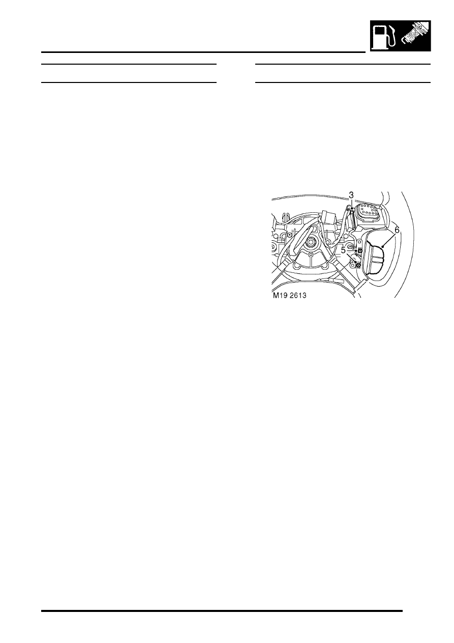
2. Remove driver's airbag module.
3. Release remote control switches multiplug and
leads from steering wheel base.
4. Disconnect remote control switches multiplug
from harness.
5. Remove 2 screws securing remote control
switches to steering wheel base.
6. Release and remove remote control switches
from steering wheel.
Refit
1. Fit remote control switches to steering wheel
and secure with screws.
2. Connect remote control switches multiplug to
harness.
3. Secure leads and multiplug to base of steering
wheel.
4. Fit driver's airbag module.
ENGINE MANAGEMENT SYSTEM - V8
18-2-88 REPAIRS
Switch - clutch pedal - cruise control
$% 19.75.34
Remove
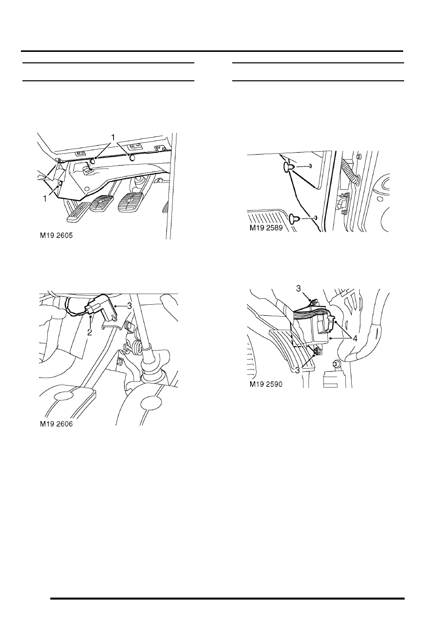
1. Remove 3 fasteners and move driver's side
lower closing panel aside.
2. Disconnect multiplug from clutch pedal switch.
3. Remove switch from pedal bracket.
Refit
1. Engage switch fully into pedal bracket location
and connect multiplug.
2. Position lower closing panel and secure with
fasteners.
ECU - Cruise control
$% 19.75.49
Remove
1. Remove fixings securing fascia RH closing
panel and remove panel.
2. Remove 2 fixings and remove 'A' post lower
trim.
3. Remove 2 nuts and remove ECU from studs.
4. Disconnect multiplug from ECU and remove
ECU.
Refit
1. Position new ECU and connect multiplug.
2. Fit ECU to studs and secure with nuts.
3. Fit lower trim panel to 'A' post and secure with
fixings.
4. Fit closing panel and secure with fixings.
5. Programme the ECU using TestBook.
FUEL DELIVERY SYSTEM - TD5
DESCRIPTION AND OPERATION
19-1-1
FUEL DELIVERY SYSTEM - Td5
DESCRIPTION AND OPERATION
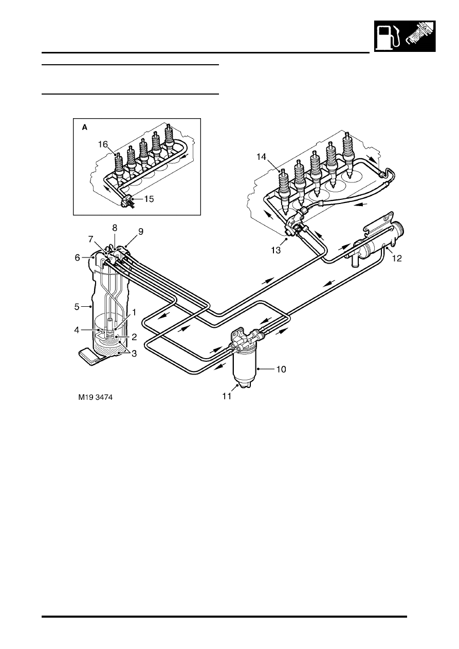
Fuel delivery system component
location
A = Pre EU3 models
1 HP stage
2 LP stage
3 Filters
4 Jet pump
5 Fuel pump and fuel gauge sender assembly
6 LP return connection
7 LP feed connection
8 HP feed connection
9 Air bleed connection
10 Fuel filter
11 Water sensor
12 Fuel cooler
13 Fuel pressure regulator (EU3 models)
14 Electronic unit injectors
15 Fuel pressure regulator (pre EU3 models)
16 Electronic unit injectors
FUEL DELIVERY SYSTEM - TD5
19-1-2
DESCRIPTION AND OPERATION
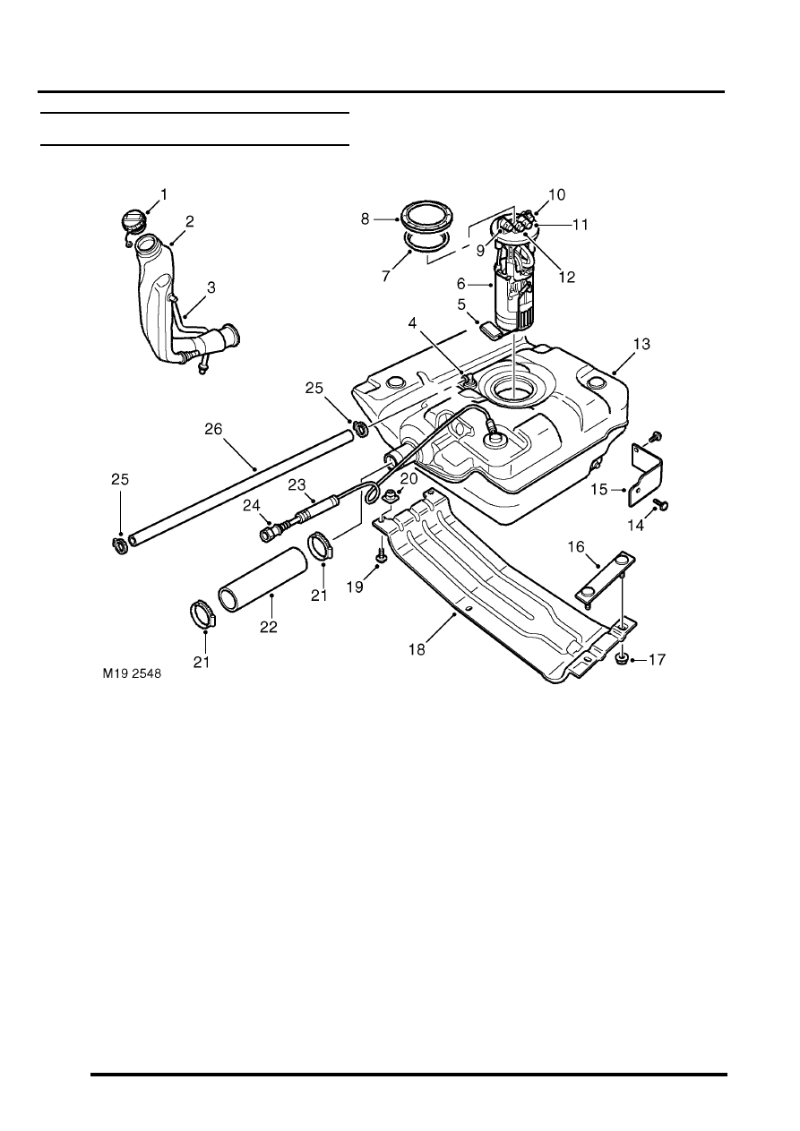
Fuel tank and breather components
1 Fuel filler cap
2 Filler tube
3 Atmospheric vent pipe
4 Tank breather connection
5 Fuel gauge sender float
6 Fuel pump and fuel gauge sender assembly
7 Seal
8 Locking ring
9 Low pressure return connection
10 Air bleed connection
11 High pressure feed connection
12 Low pressure feed connection
13 Fuel tank and breather assembly
14 Scrivet 2 off
15 Heat shield
16 Stud plate
17 Nut 2 off
18 Cradle
19 Bolt 2 off
20 Nut plate 2 off
21 Hose clip 2 off
22 Hose
23 Vent pipe
24 Vent pipe coupling
25 Hose clip 2 off
26 Breather hose
Нет комментариевНе стесняйтесь поделиться с нами вашим ценным мнением.
Текст