Discovery 2. Manual — part 357
NAVIGATION SYSTEM
DESCRIPTION AND OPERATION
87-3
Navigation Computer
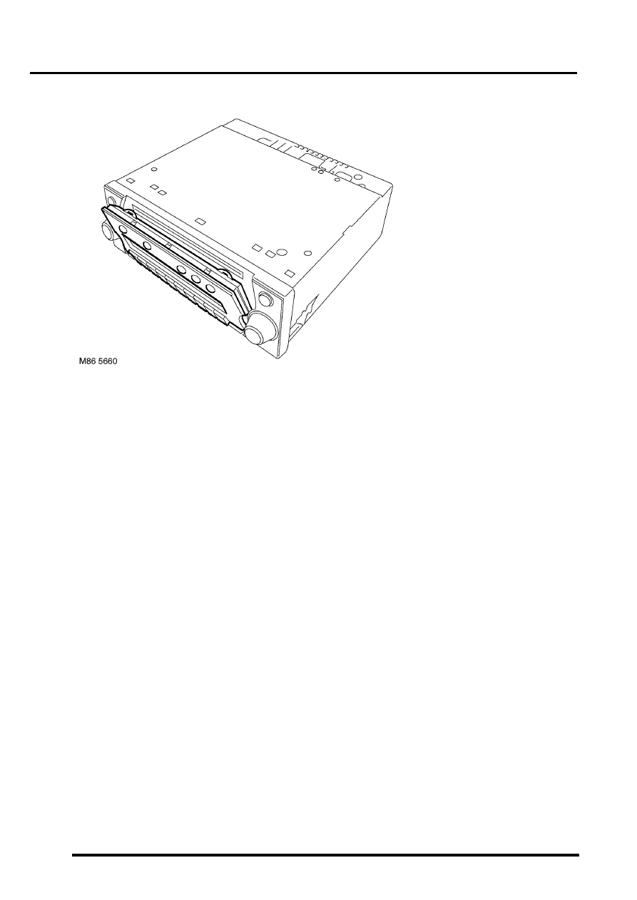
The navigation computer is installed in the DIN radio slot in the fascia. A spring loaded catch on each side of the
navigation computer secures it in position. Slide tools, installed in slots at the bottom front corners of the navigation
computer, are required to unlock the catches during removal.
The navigation computer contains all the hardware and software required for control of the navigation, radio and CD
systems, including the GPS receiver and a solid state piezo gyro for the navigation system. The piezo gyro measures
the motion of the vehicle around its vertical axis.
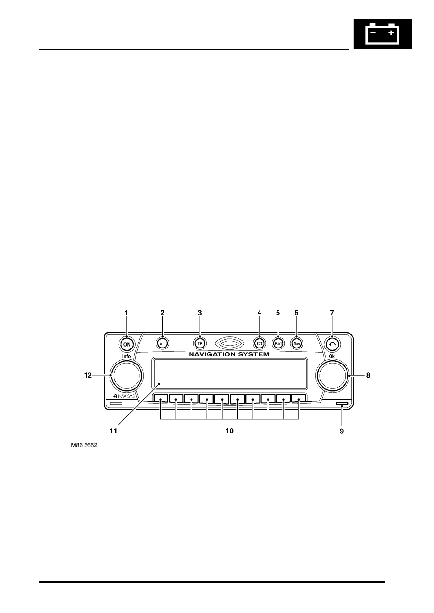
The controls for the navigation computer are all located on the front panel of the unit. The centre section of the front
panel hinges to allow access to the CD player and, for security purposes, can be removed from the unit. The controls
perform the following functions:
l
On/Off (ON) button, for switching the unit on and off.
l
Tone button, for activating the tone menu to adjust bass, treble, balance, fade and loudness functions.
l
Traffic Programme (TP) button, for activating the traffic information programme menu (Europe only).
l
Compact Disc (CD) mode button, for selecting CD operation.
l
Radio (Rad) mode button, for selecting radio operation and tuning menus.
l
Navigation (Nav) mode button, for entry and exit of the navigation menu and service mode.
l
CD eject button, opens the removable panel and ejects the CD.
l
RH rotary control, scrolls through menus when turned and enters a selection when pressed. Also mutes audio
navigation instructions when pressed in navigation mode.
l
Multifunction buttons, for entering the security code and menu selections.
l
Liquid Crystal Display (LCD), green screen that displays navigation, radio and CD information.
l
LH rotary control, adjusts volume when turned. When pressed, restores, repeats or interrupts audio navigation
instructions or provides destination details.
1 On/Off button
2 Tone button
3 Traffic programme button (Europe only)
4 CD mode button
5 Radio mode button
6 Navigation mode button
7 CD eject button
8 RH rotary control
9 Release tool slot
10 Multifunction buttons
11 LCD
12 LH rotary control
NAVIGATION SYSTEM
87-4
DESCRIPTION AND OPERATION
Inputs and Outputs
In addition to the vehicle sensor and the antenna inputs, the navigation computer also receives the following:
l
A permanent battery feed from the passenger compartment fusebox, to power the navigation function.
l
An ignition switched battery feed from the passenger compartment fusebox, to power the navigation, radio and
CD functions when the ignition switch is in positions I and II.
l
An illumination power feed for switch illumination and LCD backlighting when the exterior lights are on.
Navigation computer outputs consist of those for the ICE system speakers and to the auxiliary CD autochanger, where
fitted.
Security Code
The navigation computer is programmed with a five digit security code selected from numbers 1 to 7. If the battery or
the navigation computer are disconnected, the code is requested on the LCD the first time the navigation computer
is switched on after reconnection; this also occurs if a different removable panel is fitted.
The code is entered using the appropriate multifunction buttons. The navigation computer automatically starts to
operate when the fifth digit of the correct code is entered. If an incorrect code is entered, CODE is displayed on the
LCD to prompt another entry attempt. If an incorrect code is entered three times in succession, WAIT is displayed on
the LCD and the unit is disabled for approximately 60 minutes. If the navigation computer is switched off, the
remaining disabled time will resume when the power is restored.
Automatic Volume Control (AVC)
The AVC feature automatically increases and decreases the audio volume with increases and decreases of vehicle
road speed. The AVC feature, also known as the GAL setting, uses the vehicle speed signal from the ABS ECU and
can be turned off or adjusted to start at a different vehicle speed. The GAL setting is accessed through the User Menu
and can be set to between 0 and +15, where 0 is off and +1 to +15 progressively increase the vehicle speed at which
AVC starts to operate.

NAVIGATION SYSTEM
DESCRIPTION AND OPERATION
87-5
System Settings Menu
The system settings menu provides access to features that can be changed to suit market and personal preferences
and to navigation system operating features. On European systems, the system settings menu also includes
computer games and a currency converter. While the navigation computer is in the navigation mode, the system
settings menu can be accessed by pressing the Nav button. Using the RH rotary control, the following features can
be selected and adjusted:
l
TIME – Allows the navigation system clock to be set to local time as opposed to the Greenwich Mean Time (GMT)
transmitted from the GPS satellites. The local time setting is necessary for correct navigation on routes with time
restrictions and for Estimated Time of Arrival (ETA) calculations. The time can only be adjusted in 30 minute
steps.
l
SAVE POSITION– Allows the current vehicle position to be saved and allocated a name in the navigation
destination memory.
l
GAMES – Provides access to a selection of computer games.
l
LANGUAGE– Allows the navigation system language and voice (where applicable) to be changed.
l
ANIMATIONS– Allows the LCD animations to be switched on and off.
l
MEASURING UNIT – Allows the route guidance distances displayed on the LCD to be switched between metric
and Imperial units.
l
ANNOUNCEMENT ETA – Allows the route guidance ETA announcement to be switched on and off.
l
CALCULATE EURO – Provides access to a currency converter.
User Menu
The user menu provides access to further features that can be changed to suit personal preferences. While the
navigation computer is in navigation, radio or CD modes, the user menu can be accessed by pressing and holding
the tone button for more than 2 seconds. The user menu is displayed over two screens, which can be toggled between
using the
⇒
multifunction button. Using the appropriate multifunction button or the RH rotary control, the following
settings can be selected and adjusted:
Screen 1
l
Gal – Automatic volume control setting (see above).
l
Tel – If a handsfree telephone system is connected to the navigation computer, allows either mute (telephone
mute mode) or audio signal (telephone conversation via the ICE speakers) to be selected.
l
Lcd – The LCD can be set to appear negative, positiveor automatic. In automatic, the display will be positive or
negative, depending on the setting of the exterior lamps.
l
Led – A Light Emitting Diode (LED) in the display can be set to off or blinking. When set to blinking, the LED
flashes when the navigation computer is switched off.
l
M/S – Radio reception can be set to Stereo, Mono or Auto, to suppress interference and reflections and so
optimise reception. Stereo is for exceptionally good reception conditions. Mono is for poor reception conditions.
In auto, the normal setting, the navigation computer automatically switches between stereo and mono depending
on reception conditions.
Screen 2
l
Nav – Sets how audio navigation instructions are delivered. In onl, other audio sources are suppressed and only
the navigation instruction is output to the speakers. In mixed, the volume of any other audio source is reduced
and the volume of the navigation announcement is the same as the original audio source +/– 6 dB (adjustable).
In independ, the audio source and navigation announcement can be set to independent volume levels.
l
Aux – Used to switch auxiliary CD AF connections between Aux mode on and Aux mode off. If no CD
autochanger is installed, an external cassette or CD player can be connected to the navigation computer and
powered by switching on the auxiliary CD AF connections.
l
Cmp – Allows a compass to be shown on the LCD when route guidance is not active.
l
BeV – Used to adjust the signal tone volume. Signal tones sound to confirm storage confirmation etc. and can
be set between 0 (quiet) and +5 (loud).
NAVIGATION SYSTEM
87-6
DESCRIPTION AND OPERATION
Service Menu
The service menu provides access to details of the navigation computer hardware and software, and can be accessed
when the navigation computer is in radio mode, by simultaneously pressing the NAV button and the 10 multifunction
buttons. The following items can then be scrolled through by pressing the Nxt (next) and Prv (previous) multifunction
buttons, or turning the RH rotary control:
l
Model No.
l
Serial No.
l
Changer Reset
l
GAL
l
Radio Software
l
Radio Bolo
l
Navi Rom
l
Navi Flash
l
RTC Value
When Changer Reset is displayed, the CD autochanger (where fitted) can be reset by pressing the appropriate
multifunction button.
When the End multifunction button is pressed, the navigation computer quits the service menu and returns to radio
mode.
Garage Menu
Garage menu enables the navigation system to be tested and calibrated, and also contains a route navigation
demonstration. The garage menu is entered from the main navigation menu, as follows:
1 Press the Nav button to access the system settings.
2 Press and hold multifunction button 3, then press multifunction button 5 to display the garage menu.
The garage menu contains the following, which can be accessed using the RH rotary control:
l
CALIBRATION RIDE – Used to calibrate the navigation computer, to enable route navigation.
l
GPS INFO– Provides functional test of antenna by checking GPS reception. If functioning correctly, displays the
number of satellites being received, the date, time (Greenwich Mean Time) and the type of positional fix currently
possible.
l
CALIBRATION– Allows vehicle specific calibration data to be entered, e.g. tyre size. Also allows current
calibration to be deleted prior to re-calibrating.
NOTE: Only known calibration data should be entered. The navigation computer cannot make route
calculations if incorrect data is entered.
l
SENSORS– Allows wheel speed, reverse gear and gyro sensor inputs to be checked.
l
VERSION– Displays navigation computer hardware and software details.
l
SPEECH TEST– Performs a test of the navigation computer audio output.
l
MODULE TEST– Performs a test routine on the internal components of the navigation computer.
l
DEMO – Allows a route navigation demonstration to be run.
To quit the garage menu, press the Nav button.
Нет комментариевНе стесняйтесь поделиться с нами вашим ценным мнением.
Текст