Discovery 2. Manual — part 712
AIR CONDITIONING
DESCRIPTION AND OPERATION
82-11
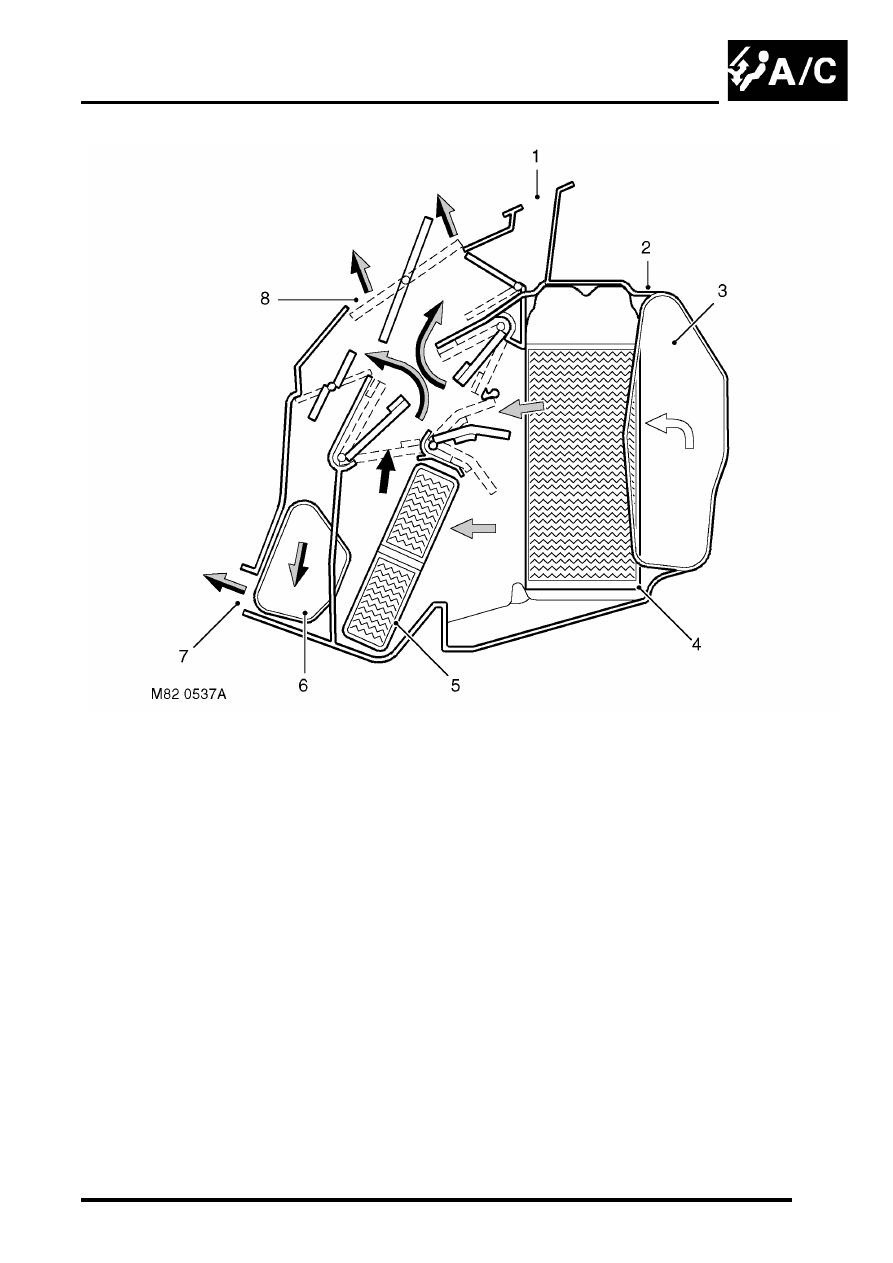
Temperature and distribution control
Figure shows flaps set for medium heat to face level and footwell outlets
1 Windscreen/Side windows outlet
2 Heater assembly casing
3 Air inlet
4 Evaporator
5 Heater matrix
6 Front footwells outlet
7 Rear footwells outlet
8 Face level outlet
AIR CONDITIONING
82-12
DESCRIPTION AND OPERATION
Control system
The control system operates the refrigerant system and the control flaps in the heater assembly to control the
temperature and distribution of air in the vehicle interior. It also outputs signals to the fresh/recirculated air servo motor
and the blower to control the volume and source of inlet air. The control system consists of:
l
An Air Temperature Control (ATC) ECU.
l
A dual pressure switch.
l
An evaporator temperature sensor.
l
An in-car temperature sensor.
l
A sunlight sensor.
l
A heater coolant temperature sensor.
l
An ambient temperature sensor.
ATC ECU
The ATC ECU is installed in the centre of the fascia, below the radio. An integral control panel on the ATC ECU
contains switches for system control inputs and a LCD to provide system status information.
Inputs from sensors and the control panel switches are processed by the ATC ECU, which then outputs the
appropriate control signals.
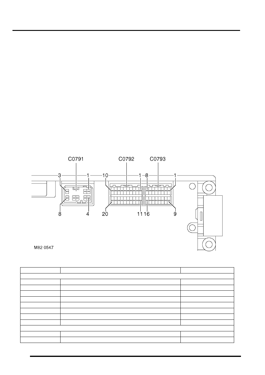
ATC ECU connectors
ATC ECU connector pin details
Connector/Pin No.
Description
Input/Output
C0791
1
Battery power supply
Input
2
Ignition power supply
Input
3
Sensor power supply
Output
4
Earth
-
5
Display illumination
Input
6
Not used
-
7
Not used
-
8
Sensor earth
-
C0792
1
Night lighting/dimming
Input
2
Vehicle speed
Input
AIR CONDITIONING
DESCRIPTION AND OPERATION
82-13
3
Hand of drive
Input
4
Distribution flaps position
Input
5
Heater coolant temperature
Input
6
External air temperature
Input
7
In-car air temperature
Input
8
Blower power transistor collector voltage
Input
9
Not used
-
10
Not used
-
11
Windscreen heater status
Input
12
Rear screen heater status
Input
13
Not connected
-
14
Driver's blend flaps position
Input
15
Passenger's blend flaps position
Input
16
LH solar heating load
Input
17
RH solar heating load
Input
18
Evaporator
Input
19
Not used
-
20
Not used
-
C0793
1
Blower power transistor base current
Output
2
Blower relay
Output
3
Windscreen heater request
Output
4
Rear screen heater request
Output
5
Passenger's blend flaps servo motor, drive to hot
Output
6
Driver's blend flaps servo motor, drive to hot
Output
7
Distribution flaps servo motor, drive to windscreen and side
windows demist
Output
8
Fresh/Recirculated air servo motor, drive to recirculated air
Output
9
Cooling fan request (diesel models)
Output
10
Power relay
Output
11
Compressor clutch request
Output
12
Cooling fan request (V8 models)
Output
13
Passenger's blend flaps servo motor, drive to cold
Output
14
Driver's blend flaps servo motor, drive to cold
Output
15
Distribution flaps servo motor, drive to footwells
Output
16
Fresh/Recirculated air servo motor, drive to fresh air
Output
Connector/Pin No.
Description
Input/Output
AIR CONDITIONING
82-14
DESCRIPTION AND OPERATION
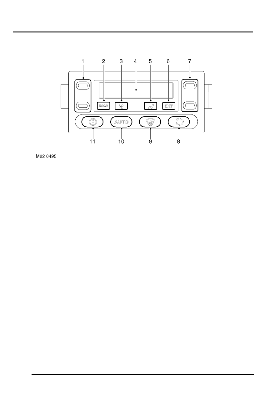
Control panel
1 LH temperature switch
2 Economy mode (ECON) switch
3 Blower switch
4 Display
5 Distribution switch
6 External air temperature (EXT) switch
7 RH temperature switch
8 Fresh/Recirculated air switch
9 Defrost mode switch
10 Automatic mode (AUTO) switch
11 A/C on/off switch
The control panel switches are all non-latching pushswitches except for the LH and RH temperature switches, which
are centre-off rocker switches. The switches have the following functions:
LH and RH temperature switches. Enabled only while the system is on:
l
Each press increases or decreases the related temperature setting, in steps of 1
°
C (2
°
F), between 16 and 28
°
C (60 and 84
°
F).
l
If the decrease side of the switch is pressed when a temperature of 16
°
C (60
°
F) is set, the display changes to
LO (maximum cold).
l
If the increase side of the switch is pressed when a temperature of 28
°
C (84
°
F) is set, the display changes to
HI (maximum hot).
l
If a switch is kept depressed, step changes occur every 0.4 seconds.
A/C on/off switch. Switches the system on and off. When used to switch the system on, the system resumes the
configuration in use prior to the previous off selection.
Blower switch. Enabled only while the system is on. Provides manual control of blower speed:
l
Each press changes the blower speed, in sequence, through off (only available if economy mode is selected on)
and five incremental speeds.
l
If the switch is kept depressed, after 1 second subsequent speed increments occur every 0.4 second until blower
reaches high speed. Releasing and then pressing the switch again changes blower back to off or low speed.
Нет комментариевНе стесняйтесь поделиться с нами вашим ценным мнением.
Текст