Discovery 2. Manual — part 168
STEERING
DESCRIPTION AND OPERATION
57-7
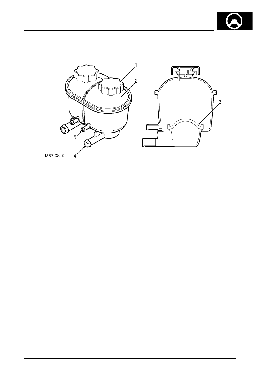
Reservoir
1 Filler cap
2 Reservoir body (dual PAS/ACE shown )
3 Filter
4 Supply connection
5 Return connection
The fluid reservoir is made of moulded plastic and is located on LH side of the engine compartment, on a bracket
which is attached to the inner wing. Dependent on the vehicles specification the reservoir may be a dual PAS/ACE,
or PAS only reservoir. Both types of reservoir are similar to each other the dual PAS/ACE reservoir has two chambers,
the PAS only reservoir has one chamber of a larger capacity. On both types of reservoir the PAS chamber has its own
filler cap and is identified by lettering on the reservoir body.
A filter of fine polyester mesh is moulded into the base of the chamber. The filter removes particulate matter from the
fluid before it is drawn into the supply connection and is non-serviceable. Upper and lower level marks are moulded
into the reservoir body, the reservoir is fitted with filler cap, a seal in the cap prevents leakage. The filler cap is pushed
onto a latch and turned through 90
°
to lock. A breather hole is incorporated in the cap to allow venting of air due to
fluid level changes during operation. The breather hole also allows air that may be in the fluid to separate out and vent
to atmosphere.
The reservoir holds hydraulic fluid and allows for expansion and contraction of the fluid due to temperature variations.
With the reservoir correctly filled the inlet to the PAS pump will be kept covered at normal operational attitudes. The
fluid flowing to the reservoir is cooled by convection from the pipe surfaces, the fluid held in the reservoir also allows
convection from the sides of the reservoir to take place. The total capacity of the reservoir with PAS only is 1000 cc
(0.264 US gallons), for vehicles fitted with PAS and ACE the total capacity of the reservoir is 500 cc (0.132 US
gallons).
STEERING
57-8
DESCRIPTION AND OPERATION
Steering box
The steering box is located behind the first cross member of the chassis and is secured to the chassis rail with four
bolts. The steering box is of the worm and roller type and has a rotary control valve. The steering box is connected to
the steering knuckles of the front road wheels by the drop arm, drag link and track rod. The steering box is lubricated
by the hydraulic fluid in the housing. The input shaft is attached to the steering wheel via the intermediate shaft and
steering column. The drop arm is secured to the output shaft with a nut and tab washer. A ball joint allows movement
between drop arm and drag link, the ball joint is secured with a locknut. The steering box requries approximately 3.5
turns from lock to lock.
As a maintenance aid, an alignment bolt can be used to lock the drop arm at the steering box centre position. The bolt
fits in a groove in the rear face of the drop arm and screws in to a threaded hole on the bottom of the steering box
housing.
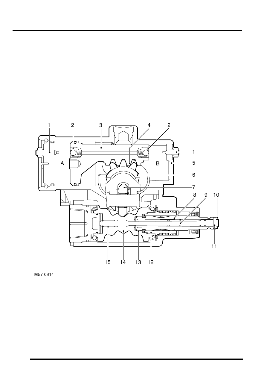
Cross section through steering box
1 Relief valve stop 2 off
2 Relief valve 2 off
3 Piston
4 Rack
5 Housing
6 Output shaft
7 Roller
8 Valve rotor
9 Torsion bar
10 Input shaft
11 Pin
12 Valve sleeve
13 Course spline
14 Worm gear
15 Spline (worm gear to torsion bar)

STEERING
DESCRIPTION AND OPERATION
57-9
Principle of operation
Movement of the input shaft is transferred through the pin to the torsion bar and valve rotor on the input shaft. As the
input shaft turns, the spline of the torsion bar turns the worm gear. This action causes the roller to rotate on its bearings
and move. As the roller is located by a pin to a yoke on the output shaft, the output shaft rotates in the steering box
housing. As the amount of torque acting on the input shaft increases the torsion bar starts to twist. As the torsion bar
twists the valve rotor turns in the valve sleeve. When the ports in the valve rotor and valve sleeve are turned, hydraulic
fluid is directed to chamber 'A' or 'B' in the power cylinder.
With hydraulic fluid in one chamber under high pressure, the piston moves. The return line ports in the rotary valve,
aligned by the movement of the valve rotor, allow the fluid in the opposite chamber to flow to return. The teeth of the
rack move and transfer the force from the piston to the output shaft, giving assistance to move the drop arm. As the
output shaft rotates the torsion bar load is decreased. The rotor on the input shaft will return as the torsion bar
unwinds, the rotary valve will then be in a neutral position and the pressure in chambers 'A' and 'B' will equalise. With
no high pressure acting on the piston, force on the piston and rack is released.
To prevent heat accumulation at full steering lock due to excessive pressure, a relief valve inside the steering box is
opened as the box approaches full lock. The relief valve pins are located in the cylinder cover and housing and are
not to be adjusted.
The steering box design ensures a mechanical link through the course spline on the control valve rotor, the spline will
become engaged if:
l
The hydraulic pressure fails.
l
The steering box rotary control valve fails.
The coarse spline may also engage in some full lock situations if sufficient torque is applied to the input shaft.
STEERING
57-10
DESCRIPTION AND OPERATION
Rotary control valve
The rotary valve assembly comprises of three parts. The valve sleeve is fixed inside one end of the worm gear, the
valve sleeve has ports through it to allow the passage of hydraulic fluid. The input shaft has a valve rotor machined
on one end, the valve rotor also has ports through it and can rotate in the valve sleeve. A torsion bar is attached to
the input shaft by a pin, the torsion bar goes through the input shaft and valve rotor and is engaged by a spline into
the worm gear.
The coarse spline on the end of the valve rotor is loosely engaged in the worm gear, the coarse spline can make
contact and drive the worm gear in some full lock and in no pressure conditions. In the event of a torsion bar failure,
power assistance will be lost, the coarse spline will drive the worm gear and enable the vehicle to be steered and
driver control maintained.
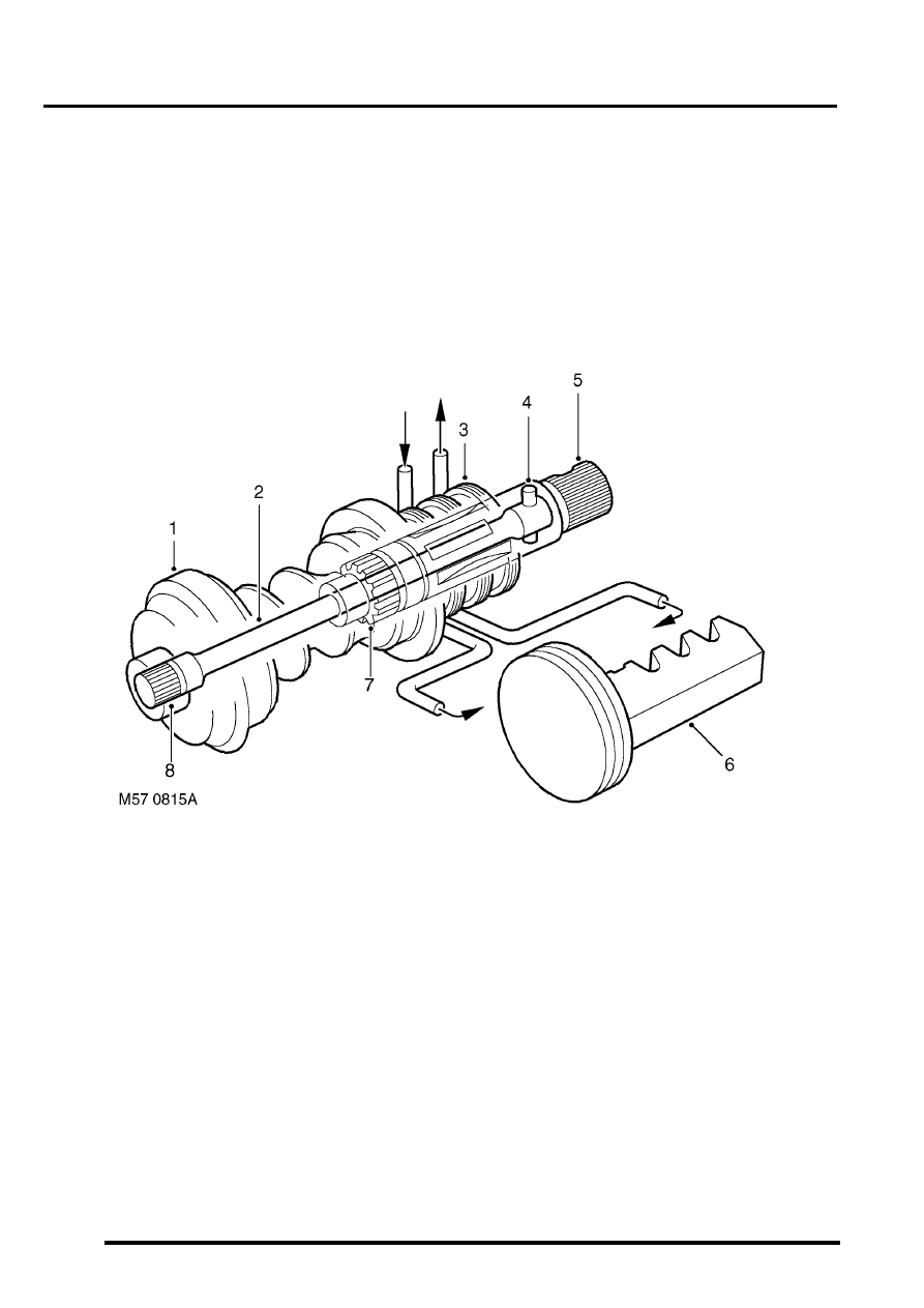
Rotary control valve at neutral
1 Worm gear
2 Torsion bar
3 Valve sleeve
4 Pin
5 Input shaft and valve rotor
6 Piston/rack
7 Coarse spline
8 Spline (torque shaft to worm gear)
When there is no demand for assistance the torsion bar holds the ports in the valve sleeve and valve rotor in a neutral
relationship to one another. The ports in the valve sleeve and the valve rotor are so aligned to allow equal (low) fluid
pressure on each side of the piston. Excess fluid flows through ports in the valve rotor through the valve sleeve and
back to the reservoir.
Нет комментариевНе стесняйтесь поделиться с нами вашим ценным мнением.
Текст