Discovery 2. Manual — part 482
ENGINE MANAGEMENT SYSTEM - V8
DESCRIPTION AND OPERATION
18-2-7
The ECM controls the following outputs:
l
Fuel injectors (1 per cylinder).
l
Ignition coils/ high tension leads/ spark plugs.
l
Fuel pump relay.
l
Idle air control valve.
l
Heated oxygen sensors.
l
EVAP canister purge valve.
l
EVAP canister vent solenoid (CVS) valve (where fitted).
l
Malfunction Indicator Lamp (MIL)/ service engine soon lamp (where fitted).
l
Hill descent control (via SLABS interface).
l
EVAP system fuel leak detection pump (where fitted)
l
Secondary air injection pump (where fitted)
The ECM also interfaces with the following:
l
Diagnostics via diagnostic connector with TestBook.
l
Controller Area Network (CAN) link to EAT ECU.
l
Air conditioning system.
l
Self Levelling & Anti-lock Braking System (SLABS) ECU.
l
Immobilisation system via the body control unit (BCU).
l
Instrument cluster.
l
Cruise control ECU
l
Active Cornering Enhancement (ACE) ECU
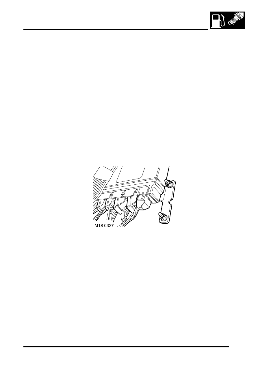
Engine Control Module (ECM)
The engine control module (ECM) is located on the RH side A post below the face panel inside the vehicle. It has a
cast aluminium case and is mounted on a bracket. The ECM has 5 independent connectors totalling 134 pins.
The ECM is available in 4 variants:
l
NAS.
l
NAS low emission vehicles.
l
UK/ Europe/ Japan/ Australia.
l
ROW/ Gulf.
The ECM uses a 'flash' electronic erasable programmable read only memory (EEPROM). This enables the ECM to
be externally configured, to ensure that the ECM can be updated with any new information, this also allows the ECM
to be configured with market specific data. TestBook must be used to configure replacement ECM's. The ECM can
be reconfigured up to 16 times to meet changing specifications and legislation.
The ECM memorises the positions of the crankshaft and the camshaft when the engine has stopped via the CKP and
CMP sensors. This allows immediate sequential fuel injection and ignition timing during cranking. This information is
lost if battery voltage is too low (i.e. flat battery). So the facility will be disabled for the first engine start.

ENGINE MANAGEMENT SYSTEM - V8
18-2-8
DESCRIPTION AND OPERATION
Input/Output
The ECM has various sensors fitted to the engine to allow it to monitor engine condition. The ECM processes these
signals and decides what actions to carry out to maintain optimum engine operation by comparing the information
from these signals to mapped data within its memory.
Connector 1 (C0634): This connector contains 9 pins and is used primarily for ECM power input and earth. The ECM
requires a permanent battery supply, if this permanent feed is lost i.e. the battery discharges or is disconnected the
ECM will lose its adapted values and its Diagnostic Trouble Codes (DTC). These adapted values are a vital part of
the engine management's rolling adaptive strategy. Without an adaptive strategy, driveability, performance, emission
control, and fuel consumption are adversely affected. The ECM can be damaged by high voltage inputs, so care must
be taken when removing and replacing the ECM.
Pin out details connector C0634
Connector 2 (C0635): This connector contains 24 pins and is primarily used for Heated Oxygen Sensors (HO
2
S)
control and earth. The HO
2
S sensors require a heater circuit to assist in heating the tip of the sensors to enable closed
loop fuelling to be implemented quickly after cold starting.
Pin out details connector C0635
Pin No.
Function
Signal type
Reading
1
Ignition position II
Input
12 V
2
Not used
-
-
3
Not used
-
-
4
Chassis earth
Earth
0V
5
Fuel injectors earth
Earth
0V
6
Power stage earth
Earth
0V
7
Permanent battery supply
Input battery supply
12V
8
Switched relay positive
Input switched
0-12V
9
Not used
-
-
Pin No.
Function
Signal type
Reading
1
HO
2
S heater RH bank - downstream
Output
PWM 12-0V
2
Not used
-
-
3
Not used
-
-
4
Not used
-
-
5
Thermostat monitoring sensor
Earth
0V
6
Not used
-
-
7
HO
2
S heater LH bank - downstream
Output
PWM 12-0V
8
HO
2
S sensor RH bank - downstream
Earth/ Signal
0V
9
HO
2
S sensor LH bank - upstream
Earth/ Signal
0V
10
HO
2
S sensor RH bank - upstream
Earth/ Signal
0V
11
HO
2
S sensor LH bank - downstream
Earth/ Signal
0V
12
Not used
-
-
13
HO
2
S heater RH bank - upstream
Output
PWM 12-0V
14
HO
2
S sensor RH bank - downstream
Input/ Signal
Analogue 0-5V
15
HO
2
S sensor LH bank - upstream
Input/ Signal
Analogue 0-5V
16
HO
2
S sensor RH bank - upstream
Input/ Signal
Analogue 0-5V
17
HO
2
S sensor LH bank - downstream
Input/ Signal
Analogue 0-5V
18
Fuel pump relay
Output
Switch to earth
19
HO
2
S heater LH bank - upstream
Output
PWM 12-0V
20
Not used
-
-
21
Thermostat monitoring sensor
Signal
Analogue 0-5V
22
Not used
-
-
23
Main relay
Output
Switch to earth
24
EVAP system leak detection pump motor (NAS
vehicles with positive pressure type, EVAP system
leak detection capability only)
Output
Switch to earth

ENGINE MANAGEMENT SYSTEM - V8
DESCRIPTION AND OPERATION
18-2-9
Connector 3 (C0636): This connector contains 52 pins and is used for most sensor and actuator inputs and outputs.
Sensor and actuator control is vital to ensure that the ECM maintains adaptive strategy
Pin out details connector C0636
Pin No.
Function
Signal type
Reading
1
Injector cylinder number 2
Output
Switch to earth
2
Injector cylinder number 5
Output
Switch to earth
3
Purge valve
Output, signal
PWM 12-0V
4
SAI vacuum solenoid valve (NAS vehicles from
2000MY only)
Output
Switch to earth
5
Not used
-
-
6
Fuel tank pressure sensor (NAS vehicles with
vacuum type, EVAP system leak detection
only)
Earth
0V
7
MAF sensor 5V supply
Output, reference
5V
8
Not used
-
-
9
MAF sensor earth
Earth
0V
10
TP sensor 5V supply
Output, reference
5V
11
Not used
-
-
12
Not used
-
-
13
Not used
-
-
14
Injector cylinder number 7
Output
Switch to earth
15
Injector cylinder number 6
Output
Switch to earth
16
SAI pump relay (NAS vehicles from 2000MY
only)
Output
Switch to earth
17
CMP sensor
Earth
0V
18
Low range switch (manual transmission only)
Input, signal
Active low
19
Not used
-
-
20
CMP signal
Input, signal
Digital switch 0-12V
21
ECT sensor
Earth
0V
22
Coolant temperature signal
Input, signal
Analogue 0-5V
23
MAF sensor signal
Input, signal
Analogue 0-5V
24
TP sensor signal
Input, signal
Analogue 0-5V
25
TP sensor earth
Earth
0V
26
Not used
-
-
27
Injector cylinder number 3
Output
Switch to earth
28
Injector cylinder number 8
Output
Switch to earth
29
Hill decent control output
Output, signal
PWM 0-12V
30
EVAP canister vent solenoid (CVS) valve (NAS
vehicles with vacuum type, EVAP system leak
detection only)
Output
Switch to earth
30
Leak detection pump solenoid (NAS vehicles
with positive pressure type, EVAP system leak
detection only)
Output
Switch to earth
31
A/C condenser fan
Output
Switch to earth
32
CKP sensor signal
Input, signal
Analogue, 0-300V peak
33
Not used
-
-
34
IAT sensor signal
Input, signal
Analogue 0-5V
35
KS, RH bank earth
Earth
0V
36
KS, RH bank signal
Input, signal
Analogue
37
Not used
-
-
38
Not used
-
-
39
Not used
-
-
40
Injector cylinder number 4
Output
Switch to earth
41
Injector cylinder number 1
Output
Switch to earth

ENGINE MANAGEMENT SYSTEM - V8
18-2-10 DESCRIPTION AND OPERATION
Connector 4 (C0637): This connector contains 40 pins and facilitates use of TestBook via the Diagnostic connector.
Also contained in this connector is the Malfunction Indicator Lamp (MIL), this instrument panel lamp informs the driver
of concerns within the engine management system.
Pin out details connector C0637
42
Idle air control valve open
Output, signal
PWM 12-0V
43
Idle air control valve close
Output, signal
PWM 12-0V
44
ECT sensor signal
Output, signal
PWM 0-12V
45
CKP sensor earth screen
Earth
0V
46
CKP sensor signal
Earth reference
0V
47
Not used
-
-
48
KS, LH bank earth
Earth
0V
49
KS, LH bank signal
Input, signal
Analogue
50
Not used
-
-
51
Not used
-
-
52
Not used
-
-
Pin No.
Function
Signal type
Reading
1
Not used
-
-
2
Not used
-
-
3
Not used
-
-
4
Not used
-
-
5
Not used
-
-
6
Not used
-
-
7
Not used
-
-
8
Low fuel level
Input, signal
Active high
9
Fuel tank pressure sensor (NAS vehicles with
vacuum type, EVAP system leak detection
capability only)
Output, reference
5V
10
Not used
-
-
11
Not used
-
-
12
Analogue fuel level (NAS vehicles with positive
pressure type, EVAP system leak detection only)
Input, signal
0-5V
13
Not used
-
-
14
Fuel tank pressure sensor (NAS vehicles with
vacuum type, EVAP system leak detection
capability only)
Input, signal
Analogue 0-5V
15
Not used
-
-
16
ATC compressor request
Input, signal
Active low
17
Engine speed output
Output, signal
PWM 0-5V
18
Not used
-
-
19
Not used
-
-
20
Malfunction indicator lamp 'ON'
Output
Switched earth
21
Not used
-
-
22
Vehicle speed signal (VSS)
Input, signal
PWM 0-12V
23
Not used
-
-
24
Not used
-
-
25
Not used
-
-
26
Not used
-
-
27
Not used
-
-
28
Not used
-
-
29
ATC compressor relay
Output
Switched earth
30
Not used
-
-
Pin No.
Function
Signal type
Reading
Нет комментариевНе стесняйтесь поделиться с нами вашим ценным мнением.
Текст