Discovery 2. Manual — part 523
MANIFOLDS AND EXHAUST SYSTEMS - TD5
REPAIRS
30-1-7
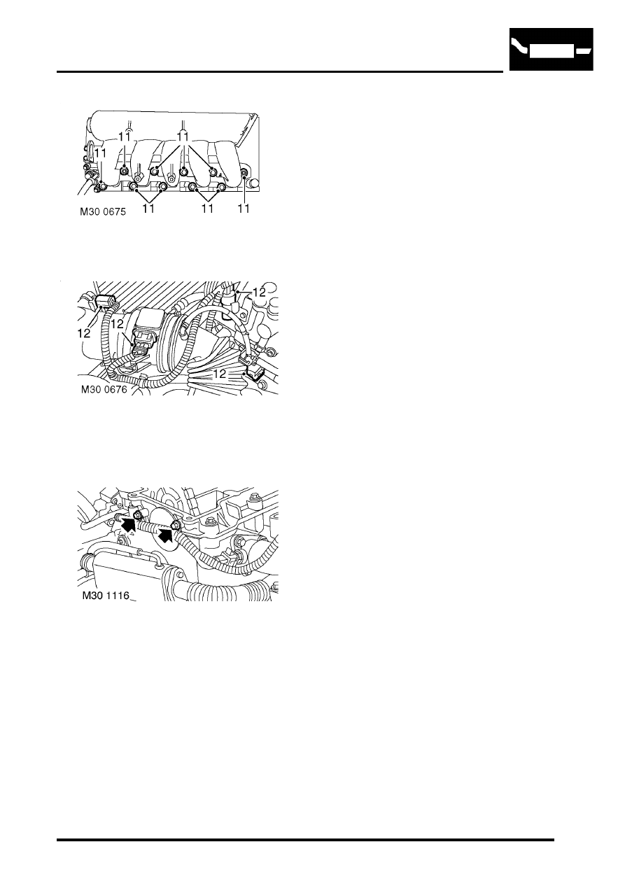
11. Remove 2 nuts and 8 bolts securing inlet
manifold to cylinder head.
12. Disconnect multiplugs from turbocharger
pressure sensor, ECT sensor, AAP sensor,
MAF sensor, A/C compressor and fuel injector
harness.
13. Remove 2 bolts securing harness to camshaft
carrier.
Note: Engine with EGR cooler illustrated.
14. Release harness from engine and inlet
manifold.
15. Remove inlet manifold and gasket.
Refit
1. Clean inlet manifold and mating faces.
2. Fit new gasket.
3. Fitinlet manifold and, working from the centre
outwards, tighten nuts and bolts to 25 Nm (18
lbf.ft).
4. Position harness to sensors and connect
multiplugs.
5. Tighten bolts securing harness clip to camshaft
carrier to 9 Nm (7 lbf.ft).
6. Clean dip stick tube and fit new 'O' ring.
7. Fit dip stick tube and tighten bolt to 9 Nm (7
lbf.ft).
8. Connect leads to glow plugs.
9. Fit alternator support bracket and tighten bolts
to 45 Nm (33 lbf.ft).
10. Position fuel cooler and tighten bolts to 25 Nm
(18 lbf.ft).
11. Fit new gasket, position EGR valve and tighten
bolts to 9 Nm (7 lbf.ft).
12. Connect multiplug to MAP sensor.
13. Fit upper fan cowl.
14. Fit engine acoustic cover.
15. Connect battery earth lead.
16. Fit battery cover.
MANIFOLDS AND EXHAUST SYSTEMS - TD5
30-1-8
REPAIRS
Gasket - exhaust manifold
$% 30.15.12
Remove
Note: The following procedure covers engines
fitted with or without an EGR cooler. The EGR
cooler is bolted to the front of the cylinder head.
1. Remove turbocharger.
2. Models with air conditioning: Remove
auxiliary drive belt.
REPAIRS, Belt - auxiliary drive.
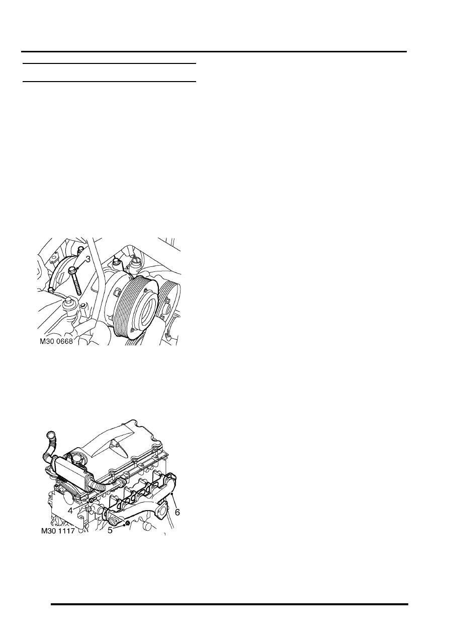
3. Models with air conditioning: Remove 4 bolts
securing compressor and move to one side.
4. Remove and discard 2 Allen screws securing
EGR pipe to exhaust manifold.
Note: Engine with EGR cooler illustrated.
5. Remove 10 nuts securing exhaust manifold to
cylinder head.
6. Remove exhaust manifold and gasket.
Refit
1. Clean exhaust manifold and mating faces.
2. Fit new gasket.Fit exhaust manifold and,
working from the centre outwards, tighten nuts
to 25 Nm (18 lbf.ft) .
3. Models with air conditioning:
Positioncompressor and tighten bolts to 25 Nm
(18 lbf.ft).
4. Position EGR valve pipe, fit new Allen screws
and tighten to 9 Nm (7 lbf.ft).
5. Fit turbocharger.
6. Models with air conditioning: Fit auxiliary
MANIFOLDS AND EXHAUST SYSTEMS - V8
DESCRIPTION AND OPERATION
30-2-1
MANIFOLDS AND EXHAUST SYSTEMS - V8
DESCRIPTION AND OPERATION
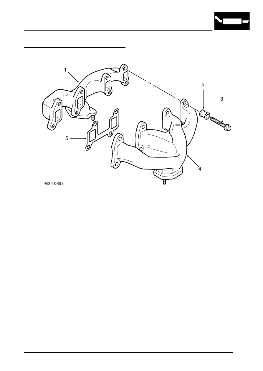
Exhaust manifold component layout
1 Exhaust manifold RH
2 Spacer 16 off
3 Torx bolt 16 off
4 Exhaust manifold LH
5 Gasket 4 off
MANIFOLDS AND EXHAUST SYSTEMS - V8
30-2-2
DESCRIPTION AND OPERATION
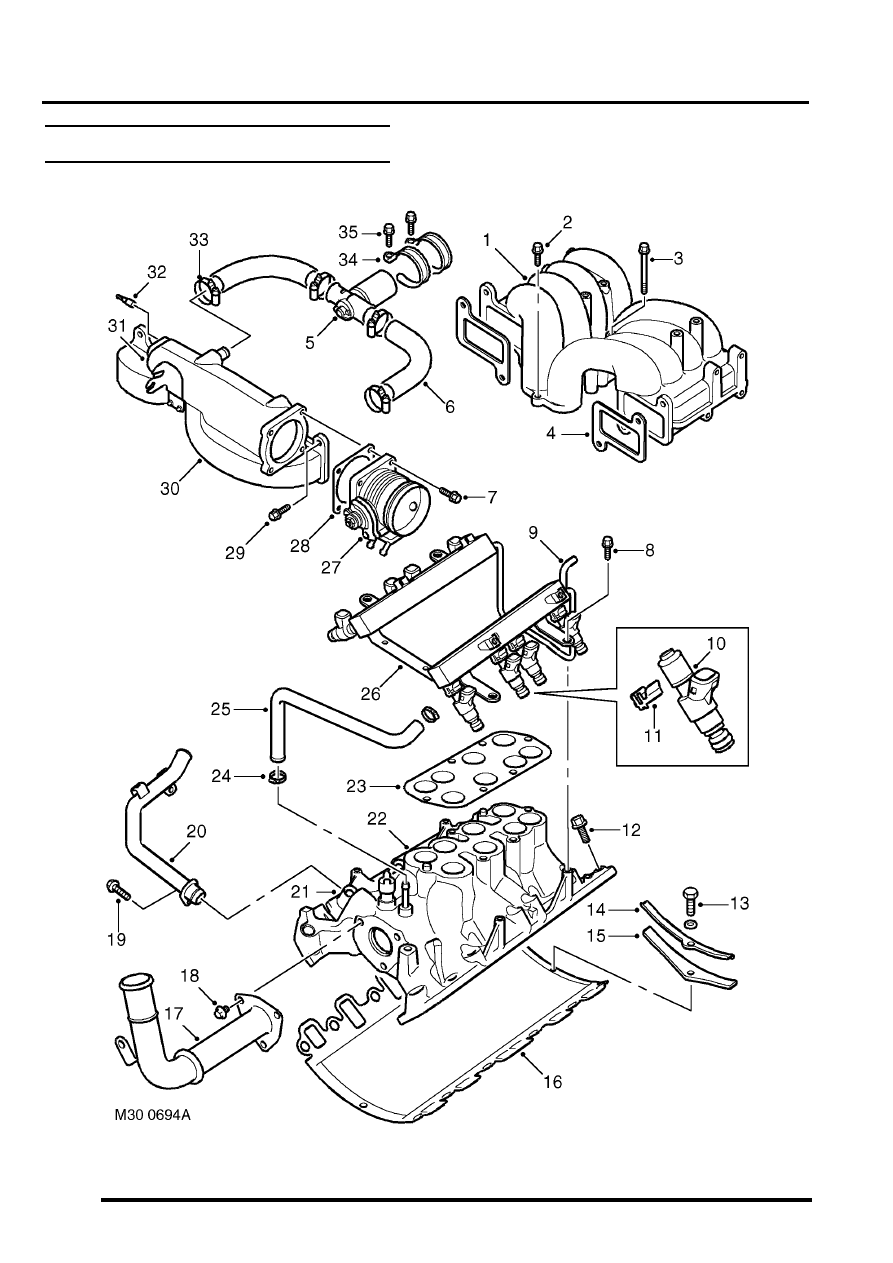
Inlet manifold component layout
Нет комментариевНе стесняйтесь поделиться с нами вашим ценным мнением.
Текст