Discovery 2. Manual — part 562
TRANSFER BOX - LT230SE
OVERHAUL
41-51
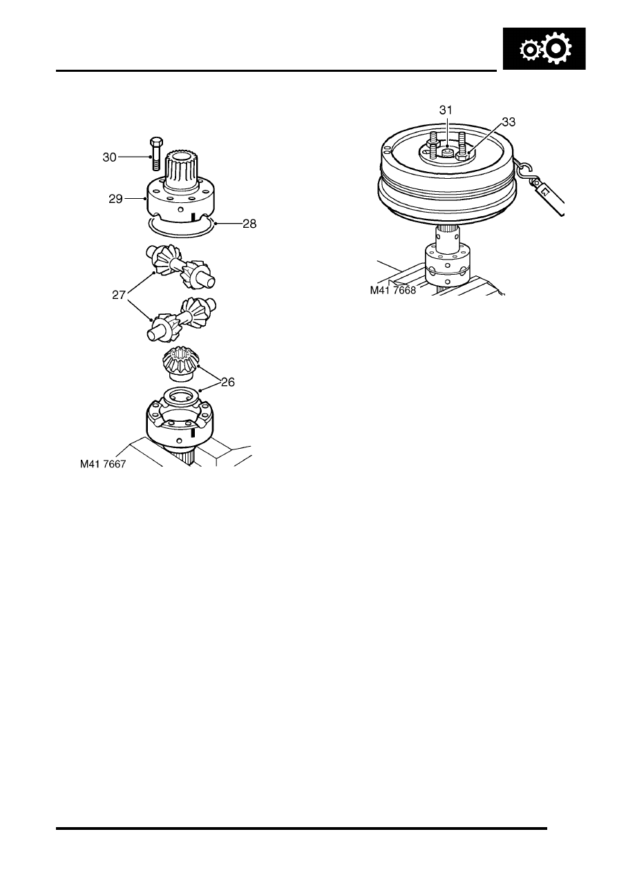
25. Remove retaining ring, then remove the planet
gears and cross shafts.
26. Fit a 1.05 mm (0.04 in) thrust washer to sun
gear from rear half of carrier. Position gear in
rear half of carrier.
27. Fit planet gears, cross shafts and dished thrust
washers to rear half of carrier. Ensure that
cross shafts are fitted correctly. Do not fit
the sun gear into the rear half carrier at this
stage.
28. Fit retaining ring.
29. Ensuring that assembly marks are aligned, fit
both halves of carrier together.
30. Fit the differential carrier bolts and, working in a
diagonal sequence, tighten the bolts to 60 Nm,
(44 lbf.ft).
31. Invert the assembly in the vice, insert the rear
output shaft into the rear half of the carrier and
check that the gears rotate freely.
32. Fit output flange on to the splines of the output
shaft, but do not fit flange nut at this stage.
33. Fit transmission brake drum to output flange
and secure the drum using 2 nuts.
34. Carry out the load to turn check, using the same
method as for the front half carrier. Record the
shim thickness when the load to turn is correct.
35. Fit the sun gear and selected thickness shim to
the front half carrier.
36. Ensuring that assembly marks are aligned, fit
both halves of carrier together.
37. Fit the differential carrier bolts and, working in a
diagonal sequence, tighten the bolts to 60 Nm,
(44 lbf.ft).
38. With differential assembled, fit rear output shaft
and brake drum, then check overall load to turn.
This should be approximately the same as the
combined load to turn figure of both front and
rear half carriers.
l
Used gears = 0.90 kg (2.0 lb)
l
New gears = 3.44 kg (7.6 lb)
TRANSFER BOX - LT230SE
41-52
OVERHAUL
Refit
1. Clean differential components.
2. Lubricate components with gearbox oil.
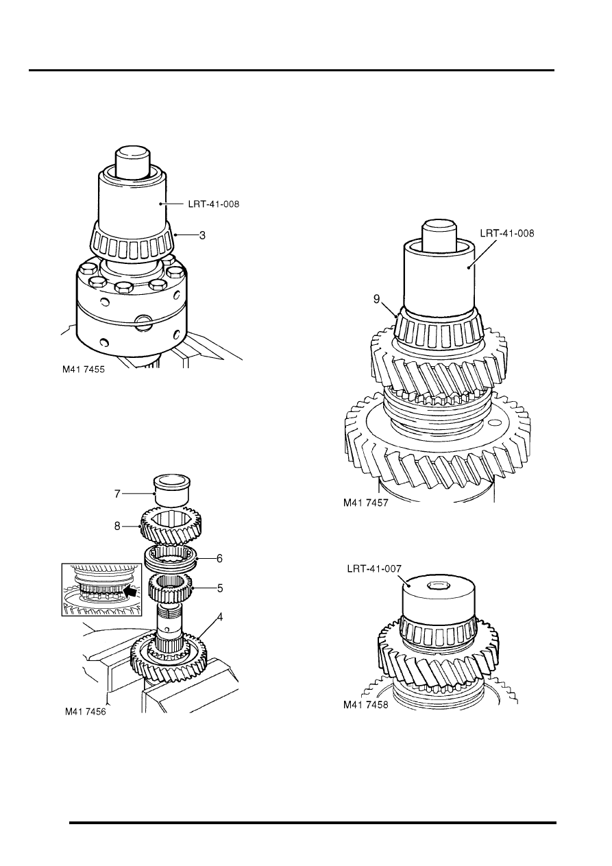
3. Position differential in soft jawed vice and fit
front bearing using tool LRT-41-008.
4. Invert differential in soft jawed vice, and fit low
range gear with dog teeth facing uppermost.
5. Fit high/low hub ensuring that machined
groove on hub teeth faces towards low range
gear.
6. Fit high/low selector sleeve ensuring that
alignment marks on hub and sleeve are
together.
7. Fit bush to high range gear ensuring collar is
uppermost.
8. Fit high range gear and bush onto shaft.
9. Fit new rear bearing using tool LRT-41-008.
10. Using tool LRT-41-007, fit new bearing
retaining nut and tighten to 72 Nm (53 lbf.ft).
Do not stake nut at this stage.
TRANSFER BOX - LT230SE
OVERHAUL
41-53
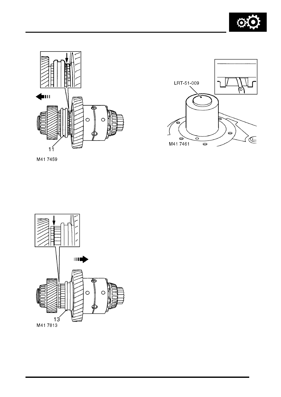
11. Using feeler gauges, determine clearance
between low range gear and high/low hub:
l
Clearance = 0.05 to 0.15 mm (0.002 to
0.006 in).
12. If clearance is not as specified, fit a new low
range gear and high/low hub and re-check.
13. Using feeler gauges, determine clearance
between high range gear and high/low hub:
l
Clearance = 0.05 to 0.15 mm (0.002 to
0.006 in).
14. If clearance is not as specified, fit new high
range gear and high/low hub and re-check.
15. Using a suitable drift, stake collar of nut into
differential shaft recess.
16. Using LRT-51-009, fit new rear bearing track
into main casing.
17. Using a straight edge and feeler gauges, check
that bearing track is recessed 1 mm (0.04 in)
below outer face of main casing.
18. Apply sealant, Part No. STC 3254 to rear
output shaft housing face.
19. Position housing to main casing.
20. Apply Loctite 290 to bolt threads fit housing to
main case bolts and tighten by diagonal
selection to 45 Nm (33 lbf.ft).
21. 03 MY only: Fit high/low selector fork and
spring to high/low selector shaft, fit retaining
clips.
CAUTION: Ensure ends of spring are fully
seated in recess in clips.
22. Position high/low selector shaft and fork to
differential ensuring that fingers of selector fork
are located in selector sleeve.
23. Position differential assembly into main casing
ensuring that splines of rear output shaft are
engaged in differential.
24. Position new differential front bearing track
ensuring that track is seated squarely.
TRANSFER BOX - LT230SE
41-54
OVERHAUL
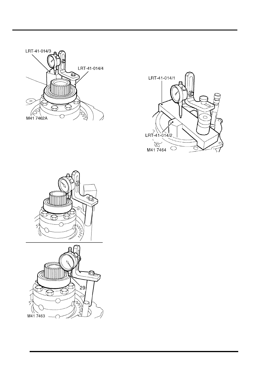
25. Position tool LRT-41-014/3 onto main casing.
26. Screw tool LRT-41-014/4 into tapped hole in
main casing and attach suitable DTI to pillar.
27. Position stylus of gauge to setting block LRT-
41-014/3 and zero gauge.
28. Position stylus onto front bearing outer track
and record reading.
29. Taking care not to disturb bearing, position
stylus on opposite side of bearing track and
record reading.
30. Obtain average of the 2 readings and record
figure.
31. Position depth block tool LRT-41-014/2 and
cross bar tool LRT-41-014/1 to front output
housing.
32. Position DTI to tool LRT-41-014/1 cross bar
and zero DTI on depth block.
33. Position DTI to cross bar and record reading
obtained.
34. Using the formula: 3.05 mm (0.120 in)+B-
A=D where: B=Height difference recorded
between depth block and cross bar.
A=Average of readings to differential front
bearing outer track. D=Thickness of shim
required to give differential bearing pre-load of
0.05 mm (0.002 in).
35. From the resultant figure obtained, select
appropriate thickness shim from the range
available.
36. Shims are available from 2.00 to 3.25 mm
(0.08 to 0.13 in) thickness, rising in increments
of 0.05 mm (0.002 in).
Нет комментариевНе стесняйтесь поделиться с нами вашим ценным мнением.
Текст