Discovery 2. Manual — part 363
NAVIGATION SYSTEM
DESCRIPTION AND OPERATION
87-27
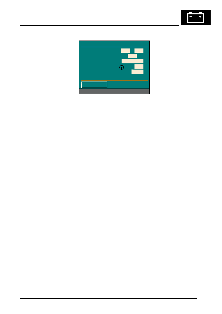
Sensor Check Menu
TestBook/T4 Diagnostics
No serial diagnostic link is provided with the CARiN III navigation system, so TestBook/T4 cannot interact with the
system.
Vehicle Position
If the vehicle’s battery has been disconnected, or if the vehicle has been transported to a new location on another
vehicle (e.g. by trailer or train), the navigation system will require up to 15 minutes to identify the new position. Entering
the vehicle’s position manually, reduces this delay. To enter the vehicle's position manually:
1 Highlight and select Information.
2 From the information menu, scroll down to the next screen and highlight and select Vehicle position.
NOTE: If the correct CD is in the navigation computer, the country is automatically entered. If you have travelled
to a new country, a new CD may be needed.
3 From the vehicle position menu, highlight and select City, then use the typewriter menu to enter the vehicle’s
position (town, road, etc.) in the same way that you would enter a destination.
4 Once the town and road names are entered, the navigation computer asks for a junction. This is the name of the
road that forms the next junction ahead of the vehicle.
5 Highlight and select Junction, then enter the name using the typewriter, or select the correct road name if a list
of names is displayed. Crossing the junction will be highlighted. Drive the vehicle in the direction of the junction
and press the rotary controller when you reach the junction.
NOTE: The vehicle position menu provides a street map facility which enables you to check your vehicle’s current
position and assists in identifying the name of the next road junction.
Provided that the information entered into the computer is correct, the navigation system requires approximately 1
minute to determine the vehicle's position.
Navigation and Trafficmaster
Road navigation and off-road navigation are accessed from the main menu by highlighting and selecting the
appropriate title with the rotary controller. In both modes of navigation, this brings up a safety notice on the display
unit. Pushing the rotary controller again accepts the safety notice and replaces it with a menu screen, which is the
entry point for operation of the navigation function. The Trafficmaster function only operates in the road navigation
mode, and is activated and de-activated by pushing and holding the menu switch for more than 0.5 second. When
activating the Trafficmaster function, the system returns to the navigation mode if the menu switch is not released
within 1.5 seconds.
Refer to the Owner Handbook: Navigation, CARiN III & Traffic Master, Publication Part No. LRL 0586ENG for full
details of how to operate the road navigation, off-road navigation and Trafficmaster functions.
M86 6074
Sensor Check
Wheel Sensors
GPS Satellites
GPS Status
GYRO
Direction of Travel
< Return
0
0
08
Position known
0285
Forward
NAVIGATION SYSTEM
REPAIRS
87-29
REPAIRS
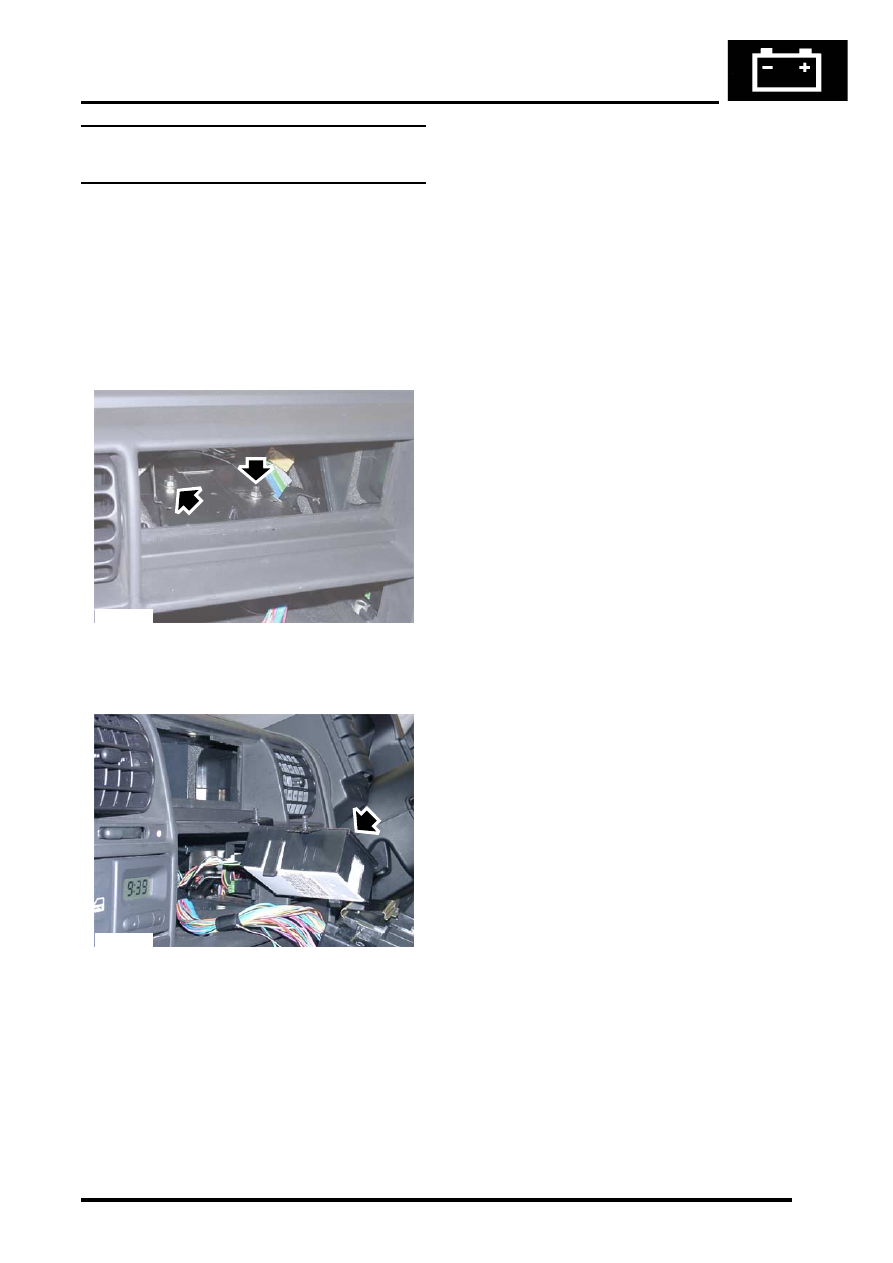
Interface electronic control unit (ECU) -
remote control
$% 86.53.15
Remove
1. Remove navigation display unit.
2. Remove automatic temperature control unit.
AIR CONDITIONING, REPAIRS, ECU
3. Remove 2 nuts securing interface carrier
bracket, carefully pull bracket out of fascia.
4. Release interface ECU from bracket,
disconnect multiplug and remove ECU.
Refit
1. Secure interface ECU in bracket and connect
multiplug.
2. Carefully position carrier bracket in fascia,
secure with nuts and tighten to 10 Nm (7 lbf.ft).
3. Fit automatic temperature control unit.
AIR CONDITIONING, REPAIRS, ECU
4. Fit navigation display unit.
M86 5760
M86 5762
NAVIGATION SYSTEM
87-30
REPAIRS
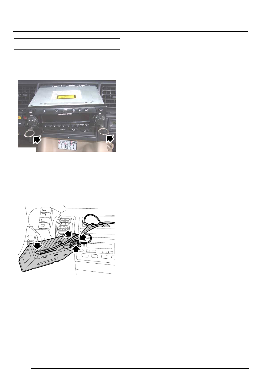
Display unit
$% 86.53.20
Remove
1. Fit tool LRT-86-009 into slots ensuring correct
handed key is in correct slot.
The tools are stamped either 'TOP L' or 'TOP
R', ensure the stamping is facing upwards
when removing the unit.
2. Pull display unit from fascia.
3. Disconnect 3 multiplugs and 2 coax cables
from display unit and remove unit.
4. Push display unit retaining clips inwards and
remove keys.
Refit
1. Position display unit to fascia, connect
multiplugs and coax cables.
2. Push display unit into fascia until retaining clips
engage.
3. Enter security code and check system is
operational.
M86 5824
M86 5825
Нет комментариевНе стесняйтесь поделиться с нами вашим ценным мнением.
Текст