Discovery 2. Manual — part 49
ENGINE - V8
OVERHAUL 12-2-69
9. Check overall dimensions of gudgeon pin.
Gudgeon pins are only supplied as an
assembly with replacement pistons.
l
Gudgeon pin length = 60.00 to 60.50 mm
(2.362 to 2.382 in).
l
Gudgeon pin diameter = 23.995 to 24.00
mm (0.9446 to 0.9448 in)
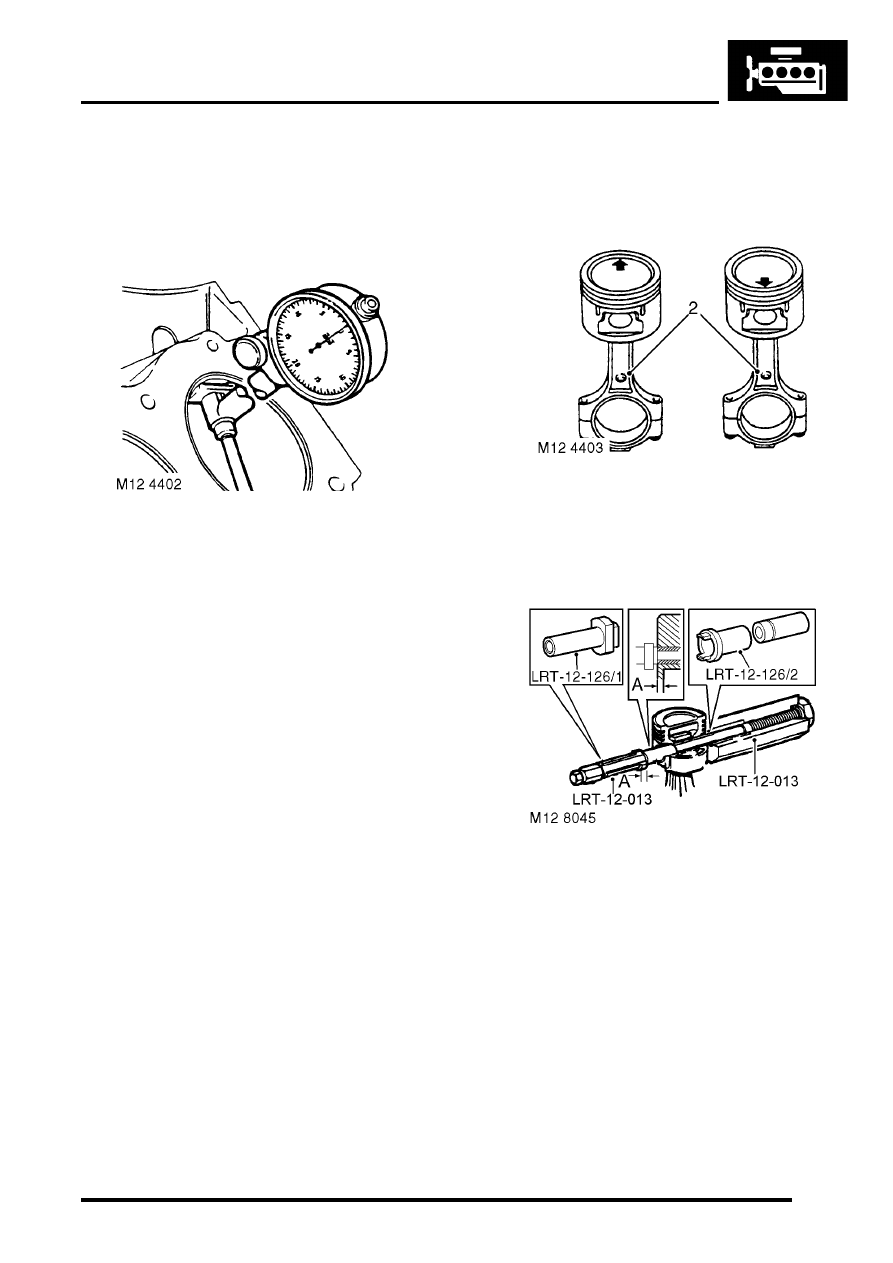
10. Measure cylinder bore wear and ovality in two
axis 40 to 50 mm (1.6 to 2 in) from top of bore.
The temperature of piston and cylinder
block must be the same to ensure accurate
measurement. Do not attempt to de-glaze
cylinder bores.
l
Grade 'A' pistons: Cylinder bore = 94.00 to
94.015 mm (3.7007 to 3.7013 in).
l
Grade 'B' pistons: Cylinder bore = 94.016 to
94.030 mm (3.7014 to 3.7019 in).
l
Maximum ovality = 0.013 mm (0.0005 in).
11. Check alignment of connecting rods.
Reassembly
1. Pistons have a 5 mm (0.2 in) offset gudgeon pin
which can be identified by an arrow mark on
the piston crown. This arrow must always point
towards the front of the engine.
2. Assemble pistons to connecting rods with
arrow on piston pointing towards domed
shaped boss on connecting rod for RH bank of
cylinders and arrow pointing away from domed
shaped boss for LH bank of cylinders.
3. Clamp hexagon body of tool LRT-12-013 in
vice.
4. Screw large nut back until flush with end of
centre screw.
5. Locate remover/replacer adapter LRT-12-126/
2 with its long spigot inside bore of hexagon
body.
6. Fit parallel sleeve, part of tool LRT-12-013,
ensuring that grooved end is towards open end
of tool LRT-12-013. Position sleeve up to
shoulder of centre screw.
7. Lubricate gudgeon pin and bores of connecting
rod and piston with graphite oil.
8. Locate connecting rod and piston to centre
screw with connecting rod entered on parallel
sleeve, part of LRT-12-013 up to the machined
groove on the sleeve.
ENGINE - V8
12-2-70 OVERHAUL
9. Fit gudgeon pin on to centre screw and into
piston bore up to connecting rod.
10. Fit remover/replacer bush LRT-12-126/1 with
flanged end towards gudgeon pin.
11. Screw the stop nut on to centre screw and
position piston against groove of tool LRT-12-
126/2.
CAUTION: Ensure that prongs of tool LRT-
12–126/2 remain in contact with piston and
do not contact gudgeon pin.
12. Lock the stop nut securely with the lockscrew.
13. Lubricate centre screw threads and thrust race
with graphite oil, screw large nut up to tool
LRT-12-013.
14. Set torque wrench to 16 Nm (12 lbf.ft) and using
socket on large nut, pull gudgeon pin in until
flange of remover/replacer bushLRT-12-126/1
is 0.40 mm (0.016 in), dimension 'A' from
face of piston. If torque is exceeded during this
procedure, fit of gudgeon pin to connecting rod
is not acceptable and components must be
replaced.
CAUTION: The centre screw and thrust race
must be kept well lubricated throughout the
operation.
15. Dismantle tool, remove piston and check no
damage has occurred during pressing and that
piston moves freely on gudgeon pin.
16. Remove compression rings, oil control rails
and expander from new piston.
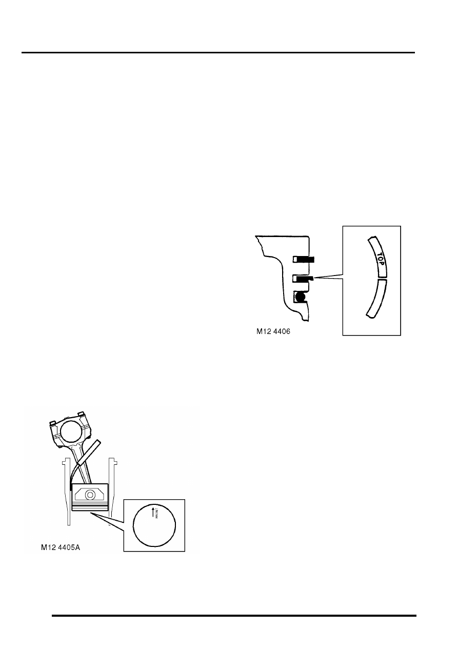
17. Invert piston and with arrow pointing towards
rear of cylinder block, insert piston into cylinder
liner.
18. Position piston with bottom of skirt 30 mm (1.12
in) from top cylinder liner.
19. Using feeler gauges, measure and record
clearance between piston and left hand side of
cylinder- viewed from the front of cylinder
block.
l
Piston to bore clearance = 0.020 to 0.045
mm (0.001 to 0.002 in).
20. Insert piston rings into cylinder bore, use the
piston to hold the rings square to bore and
check the ring gap.
l
1st compression ring = 0.30 to 0.50 mm
(0.012 to 0.02 in).
l
2nd compression ring = 0.40 to 0.65 mm
(0.016 to 0.026 in).
l
Oil control ring rails = 0.38 to 1.40 mm
(0.015 to 0.055 in).
21. Remove piston rings from bore.
22. Fit oil control ring rails and expander, ensuring
ends butt and do not overlap.
23. Fit 2nd compression ring marked 'TOP' with
marking uppermost in 2nd groove.
24. Fit 1st compression ring in first groove either
way round.
25. Check piston ring to groove clearance.
l
1st compression ring = 0.05 to 0.10 mm
(0.002 to 0.004 in).
l
2nd compression ring = 0.05 to 0.10 mm
(0.002 to 0.004 in).
26. Position oil control expander ring joint and ring
rail gaps all at one side, between gudgeon pin
and away from LH side of piston - viewed from
front of piston. Position the gaps in ring rails
approximately 25 mm (1.0 in) each side of
expander ring joint.
27. Position compression rings with gaps on
opposite side of piston between gudgeon pin
and RH side of piston - viewed from front of
piston.
28. Thoroughly clean cylinder bores.
29. Lubricate piston rings and gudgeon pin with
clean engine oil.
30. Lubricate cylinder bore with clean engine oil.
ENGINE - V8
OVERHAUL 12-2-71
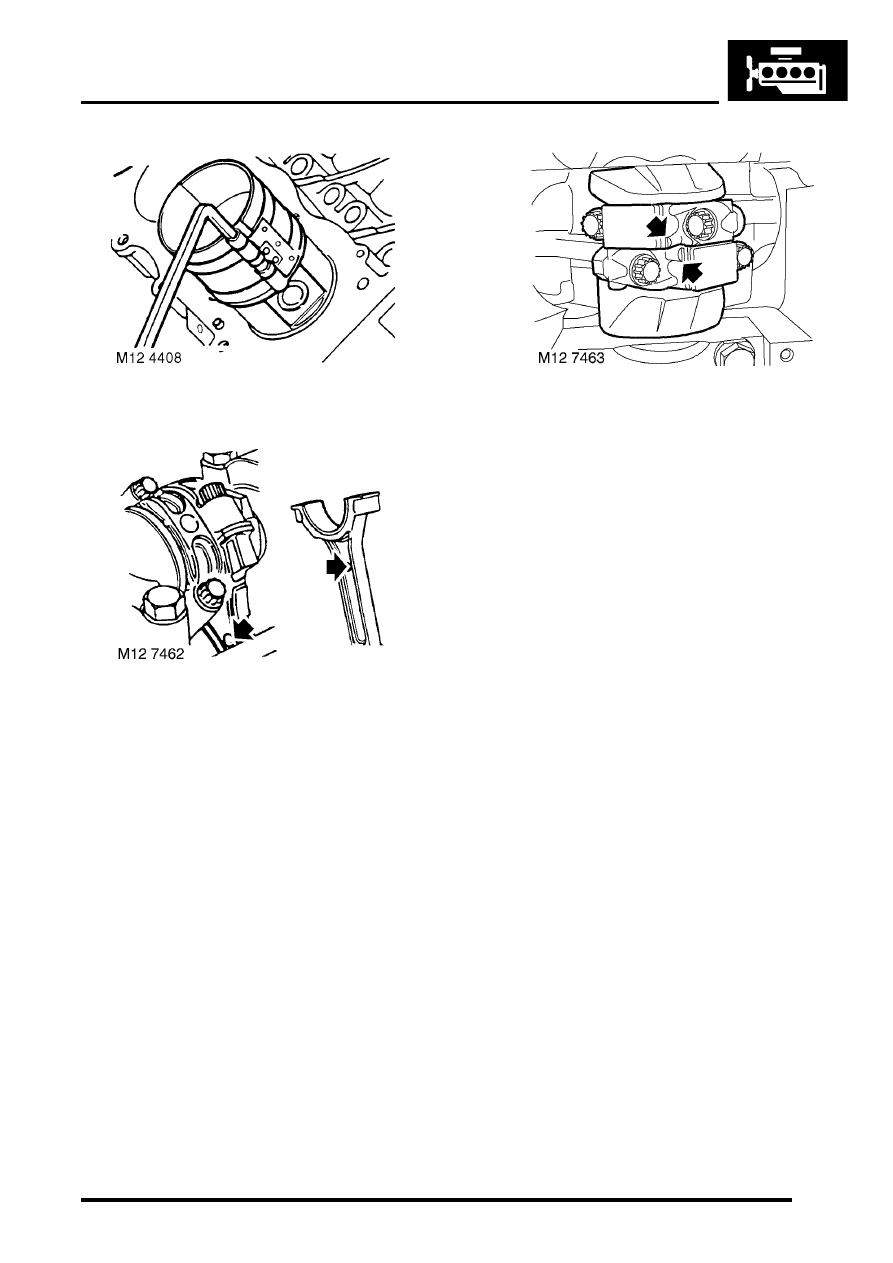
31. Using LRT-12-204, compress piston rings.
32. Insert connecting rod and piston into its
respective cylinder bore, ensuring domed
shaped boss on connecting rod faces towards
front of engine on RH bank of cylinders and
towards rear on LH bank of cylinders.
33. Clean connecting rod journal and bearing cap.
34. Lubricate connecting rod journal and
connecting rod bearings.
35. Fit connecting rod bearings and connecting rod
bearing caps ensuring they are in their correct
fitted order.
NOTE: The rib on the edge of the bearing cap
must face towards the front of the engine on the
RH bank of cylinders and towards the rear on
the LH bank.
36. Fit bolts and tighten to 20 Nm (15 lbf.ft) then
turn a further 80
°
.
37. Fit oil pick-up strainer.
ENGINE - V8, OVERHAUL, Strainer
38. Fit cylinder head gasket.
ENGINE - V8
12-2-72 OVERHAUL
Bearings - connecting rods
$% 12.17.16.01
Disassembly
1. Remove oil pick up strainer.
ENGINE - V8, OVERHAUL, Strainer
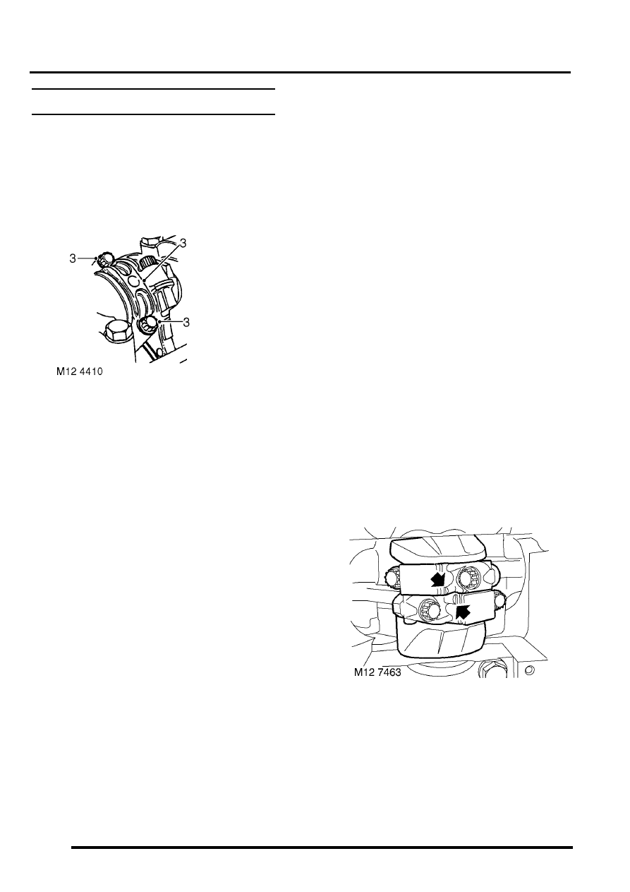
2. Suitably mark cylinder reference number on
each connecting rod bearing cap.
3. Remove 2 bolts securing each connecting rod
bearing cap, remove caps and recover
connecting rod bearings.
CAUTION: Keep bearing caps, bearings and
bolts in their fitted order.
4. Push each connecting rod up cylinder bore
until connecting rods are clear of crankshaft
journals.
CAUTION: Ensure that connecting rods do
not contact cylinder bores.
5. Remove bearing shells from each connecting
rod.
Inspect
1. Clean crankshaft journals and bearing
locations in connecting rods.
2. Inspect connecting rod bearings for wear and
renew if necessary. Connecting rod bearings
are available in two oversizes.
l
Connecting rod bearing 1st oversize = 0.254
mm (0.01 in).
l
Connecting rod bearing 2nd oversize =
0.508 mm (0.02 in).
3. Check crankshaft big-end journals for wear and
scoring. Measure for ovality; taking 3
measurements at 120
°
intervals at each end
and at centre of journals.
l
Standard journal = 55.500 to 55.513 mm
(2.20 to 2.22 in).
l
1st undersize journal - 0.254 mm (0.01 in) =
55.246 to 55.259 mm (2.17 to 2.18 in).
l
2nd undersize journal - 0.508 mm (0.02 in)
= 54.992 to 55.005 mm (2.16 to 2.165 in).
l
Journal - max. ovality = 0.040 mm (0.002 in)
Reassembly
1. Clean connecting rod caps.
2. Lubricate connecting rod journals and bearing
shells with clean engine oil.
3. Fit bearing shells to connecting rods and caps.
4. Rotate crankshaft until connecting rod journals
are correctly positioned.
5. Taking care not to displace bearing shells, pull
connecting rods on to crankshaft journals.
6. Check that bearing shells are correctly located
in connecting rod bearing caps.
7. Fit connecting rod bearing caps, ensuring that
they are in their correct fitted order.
NOTE: The rib on the edge of the bearing cap
must face towards the front of engine on the RH
bank of cylinders and towards the rear on the
LH bank.
8. Lightly oil threads of connecting rod bolts. Fit
connecting rod bolts and tighten to 20 Nm (15
lbf.ft) then turn a further 80
°
.
Нет комментариевНе стесняйтесь поделиться с нами вашим ценным мнением.
Текст