Discovery 2. Manual — part 162
REAR AXLE
OVERHAUL
51-11
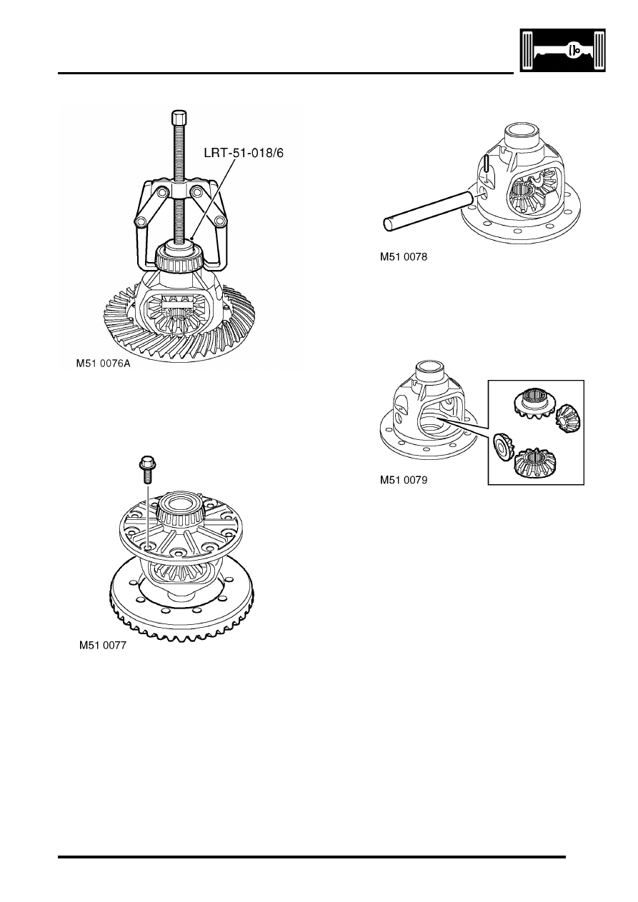
16. Using a two legged puller and LRT 51-018/6,
remove the differential bearings.
17. Secure the crown wheel assembly in a vice.
18. Remove and discard 10 bolts securing the
crown wheel to carrier.
19. Carefully remove the crown wheel from the
carrier.
20. Remove and discard roll pin securing carrier
cross shaft and remove cross shaft.
21. Rotate gears to the open part of carrier and
remove planet gears.
22. Remove sun gears.
REAR AXLE
51-12
OVERHAUL
Inspect
1. Clean and inspect all components for wear and
damage.
2. Fit planet gears and rotate to align cross shaft
holes.
3. Fit cross shaft, ensure roll pin hole is aligned.
4. Secure cross shaft with new roll pin.
5. Fit crown wheel to carrier, fit new bolts and
tighten to 60 Nm (44 lbf.ft).
6. Ensure original head bearing shim is clean and
free from burrs and fit under bearing race.
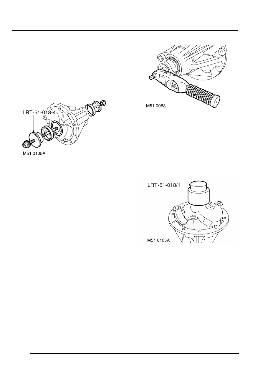
7. Ensure pinion bearing cup recesses are clean
and free of burrs and using LRT-51-018-4 fit
pinion head and tail bearing races.
8. Fit pinion head bearing to pinion.
9. Lubricate bearings with thin oil.
10. Ensure original tail bearing shim is clean and
free from burrs and fit under bearing race.
11. Fit pinion and pinion tail bearing.
12. Fit pinion flange, washer and bolt.
13. Use LRT-51-003 to restrain pinion flange.
14. Tighten pinion flange bolt to 100 Nm (74 lbf.ft).
15. Check pinion for end float. Should read zero.
16. Rotate pinion several times to settle bearings,
check pinion Torque to Turn. Torque to Turn
should be recorded during pinion rotation.
Pinion Torque to Turn should be 4 to 6 Nm (3 to
4.5 lbf.ft).
17. Adjust size of tail bearing shim to obtain correct
pinion Torque to Turn (0.025 mm = 1 Nm
(0.001' = 0.7 lbf.ft) approximately).
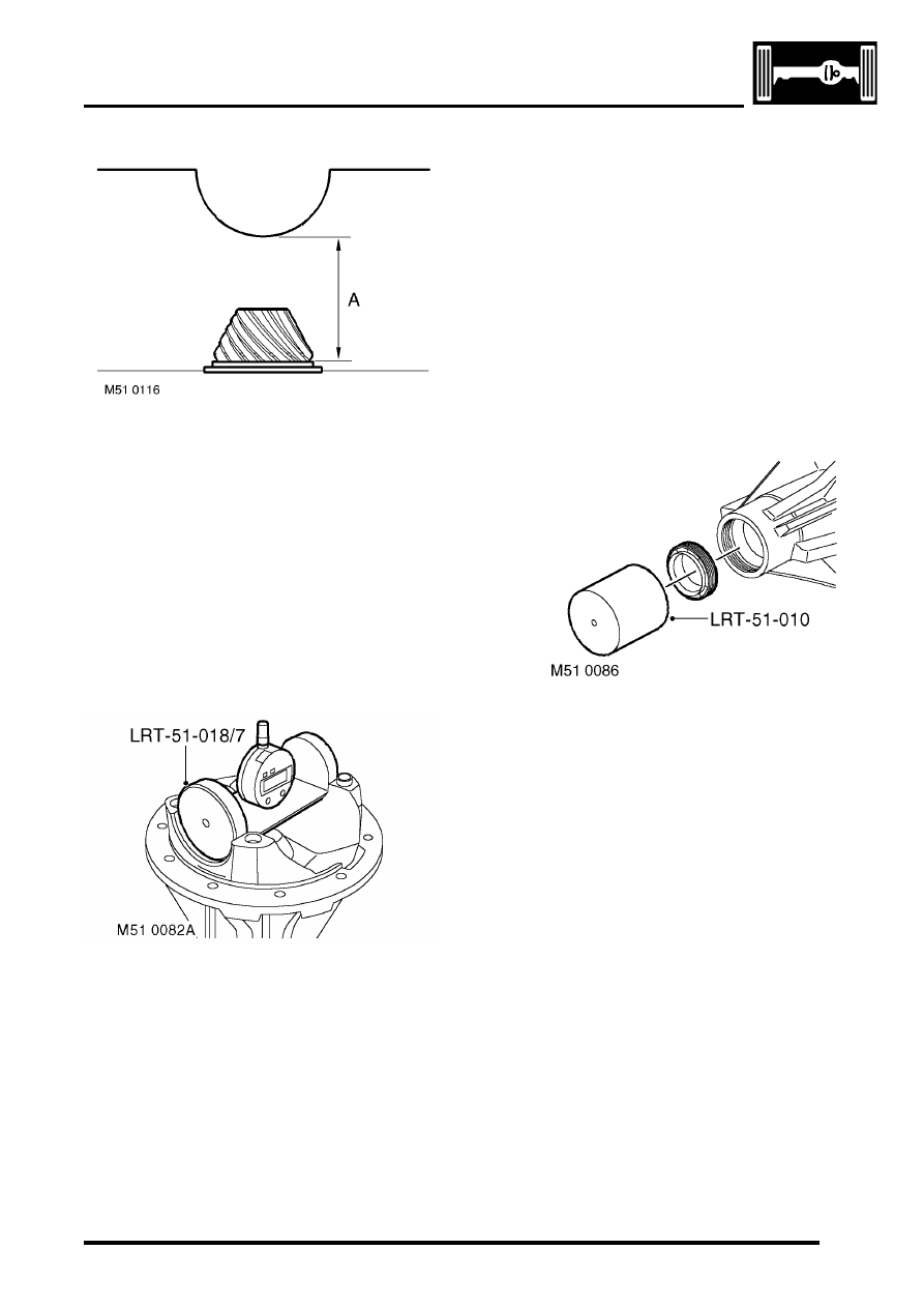
18. Position LRT-51-018-7 on surface plate,
establish zero and reference DTI.
19. Ensure pinion height setting block, setting
gauge and mating faces are clean and free
from burrs.
20. Locate setting block LRT-51-018/11 over
pinion head, ensure it is fully seated in position.
REAR AXLE
OVERHAUL
51-13
21. Pinion height setting procedure:
l
'A' = Nominal pinion height setting, 74.390.
l
'B' = Setting block height.
l
'C' = Head height setting.
l
'C' = 'A' - 'B'. Subtract nominal pinion height
'A' from setting block height 'B' (on side of
setting block).
l
Example: 74.390 - 73.130 = 1.26 mm
(2.929' - 2.88' = 0.049'). Therefore pinion
head height reading is 1.260 mm
±
0.025
mm (0.049'
±
0.001').
CAUTION: Setting block height must be
checked using figures on side of block.
22. Align setting gauge LRT-51-018/7 to setting
block, rock gauge to obtain minimum reading. If
reading is lower than required reading,
decrease shim size. If reading is higher than
required reading, increase shim size.
23. Using LRT-51-003 to restrain pinion flange,
remove bolt and washer. Remove pinion
flange.
24. Remove pinion, collect tail bearing and tail
bearing shim.
25. Remove pinion head bearing outer race and
shim. Discard shim. Ensure bearing race
recess is clean and free from burrs.
26. Fit calculated shim, and using LRT-51-018/4 fit
head bearing outer race.
27. Fit pinion, pinion tail bearing and tail bearing
shim.
28. Fit pinion flange and bolt and washer. Using
LRT-51-003 to restrain pinion flange, tighten
bolt to 100 Nm (74 lbf.ft).
29. Rotate pinion in both directions to settle
bearings.
30. Recheck pinion Torque to Turn, adjust if
necessary.
31. Recheck pinion head height.
32. Using LRT-51-003 to restrain pinion flange,
remove bolt and washer. Remove pinion
flange.
33. Discard bolt.
34. Using LRT-51-010 fit pinion seal.
35. Ensure spacer and tail bearing are correctly
located.
36. Fit pinion, pinion flange and washer.
37. Fit new pinion flange bolt and tighten to 100 Nm
(74 lbf.ft).
38. Lightly oil differential bearings.
39. Ensure spring dowels are fitted in bearing caps.
40. Fit differential bearing outer races and locate
differential assembly into housing.
41. Fit bearing caps and tighten bolts to 10 Nm (7.5
lbf.ft).
REAR AXLE
51-14
OVERHAUL
42. Fit adjusting nuts, tighten crown wheel side nut
to 22 Nm (16 lbf.ft). Ensure opposing nut is
loose.
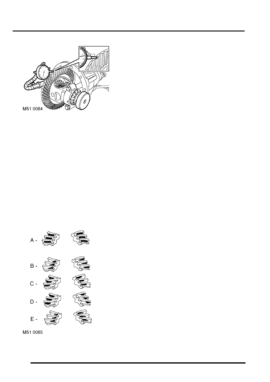
43. Position DTI to check crown wheel backlash.
Adjust opposing nut to obtain correct crown
wheel backlash.
44. Rotate pinion in both directions to settle
bearings.
45. Measure in 3 places to obtain correct crown
wheel backlash.
NOTE: Crown wheel backlash should be within
0.076 mm - 0.177 mm (0.003' - 0.007').
46. Align adjusting nuts to next roll pin slot, do not
loosen nuts to align slots.
47. Tighten bearing cap bolts to 90 Nm (66.5 lbf.ft).
48. Secure adjusting nuts with new roll pins.
49. Apply Prussian Blue to crown wheel teeth to
check tooth contact.
50. Rotate pinion several times to obtain full tooth
contact.
51. A = Normal pattern, the drive pattern should be
centred on the gear teeth. The coast pattern
should be centred on the gear teeth but may be
towards the toe. There should be some
clearance between the pattern and the top of
the gear teeth.
52. B = Backlash correct, thinner pinion shim
required.
53. C = Backlash correct, thicker pinion shim
required.
54. D = Pinion shim correct, decrease backlash.
55. E = Pinion shim correct, increase backlash.
56. Note assembly Torque to Turn when checking
tooth contact. Total Torque to Turn should not
exceed 10.85 Nm (8 lbf.ft).
Reassembly
1. Fit differential assembly.
Нет комментариевНе стесняйтесь поделиться с нами вашим ценным мнением.
Текст