Land Rover Engine 2.0 Litre T Series. Manual — part 15

ENGINE
OVERHAUL
45
Crankshaft - refit
1. Lubricate new main bearing shells with engine
oil and fit to cylinder block and main bearing
caps.
NOTE: Front, centre and rear main bearing
shells have an oil groove, intermediate
main bearing shells are plain.
2. Lubricate thrust washer halves with engine oil
and fit to cylinder block and centre main
bearing cap with the oil grooves facing away
from the cap.
NOTE: The two tagged thrust washers are
fitted in main bearing cap.
3. Lubricate crankshaft journals with engine oil
and using assistance, position crankshaft in
cylinder block.
4. Fit main bearing caps and shells.
NOTE: Bearing caps are numbered from 1
to 5 with Number 1 bearing cap being
nearest to front of cylinder block Ensure
arrows on bearing caps point towards front.
5. Lightly oil main bearing cap bolts.
6. Fit main bearing cap bolts in their original fitted
order and starting from centre main bearing
cap and working outwards, tighten bolts
progressively to 110 Nm.
7. Fit 2 Woodruff keys in crankshaft.
8. Fit big-end bearings.
ENGINE
46
OVERHAUL
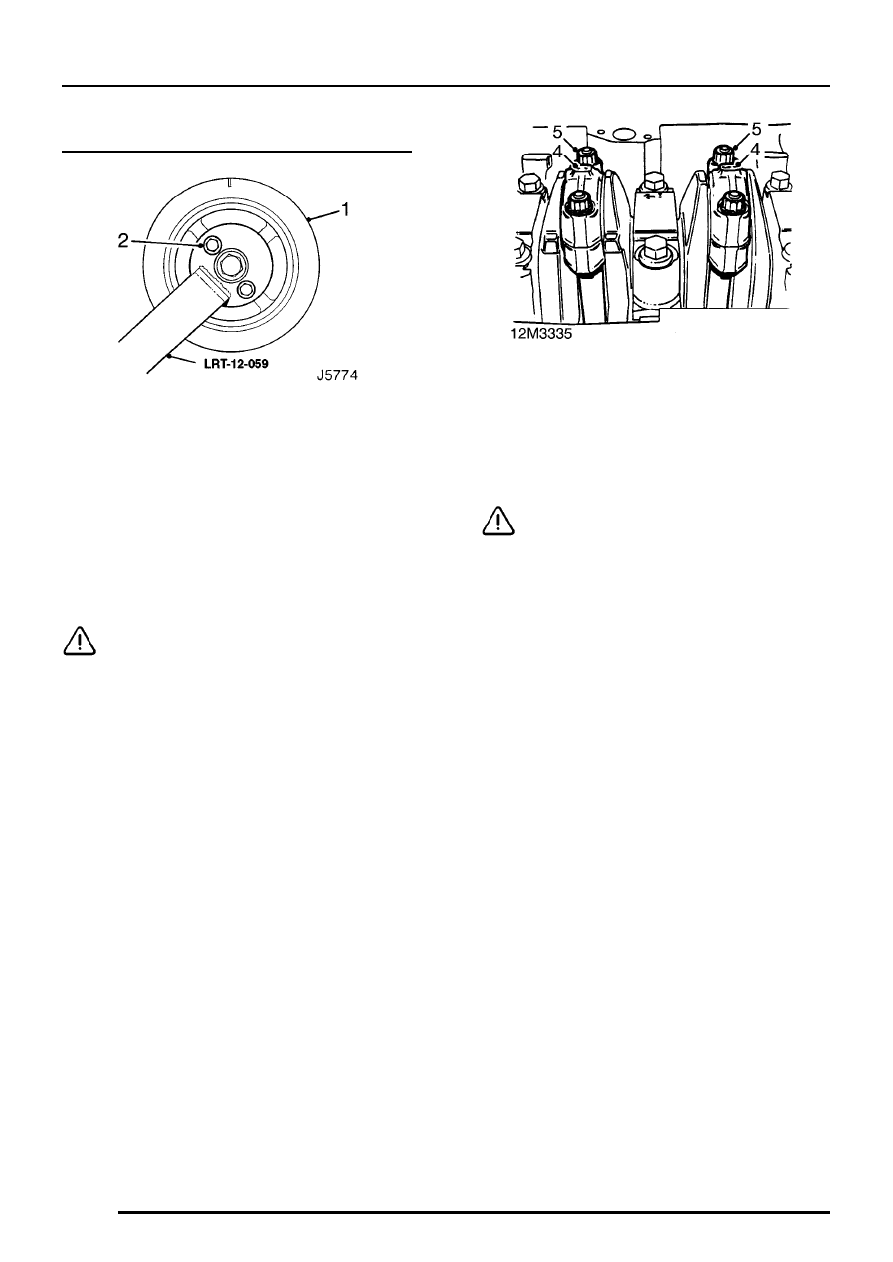
Big-end bearings - refit
1. Temporarily fit timing gear, crankshaft pulley
and holding tool LRT-12-059 to crankshaft.
2. Use 2 pulley bolts to retain tool.
3. Lubricate new big-end bearing shells and
crankshaft journals with engine oil.
4. Rotate crankshaft to bring numbers 2 and 3
big-end journals to BDC, pull connecting rods
on to journals and remove plastic sleeving from
bolts.
CAUTION: Do not rotate crankshaft more
than 45
°
in any direction.
5. Fit big-end bearing caps and shells to their
respective connecting rods ensuring that
reference marks are aligned.
6. Fit and tighten big-end bearing cap nuts to 55
Nm.
CAUTION: Ensure nuts are fitted in their
original locations.
7. Repeat above procedures for numbers 1 and 4
big-end bearings.
8. Remove holding tool LRT-12-059.

ENGINE
OVERHAUL
47
Gearbox adaptor plate - refit
1. Position gearbox adaptor plate on locating
dowels.
2. Fit 4 Torx screws and tighten to 45 Nm.
3. Fit 2 bolts and tighten to 90 Nm.
Crankshaft rear oil seal - refit
1. Remove all traces of oil from oil seal running
surface on crankshaft and tool LRT-12-061.
2. Check that oil seal bolt holes in cylinder block
are clean and dry.
3. Position tool LRT-12-061 on crankshaft.
NOTE: If oil seal protector is supplied with
new oil seal, this should be used as an
alternative to LRT-12-061.
4. Taking care not to touch sealing lip of oil seal,
slide seal and housing on to crankshaft.
CAUTION: Do not lubricate oil seal or
running surface on crankshaft.
5. Position oil seal and housing on cylinder block.
6. Fit bolts and working in sequence shown,
tighten to 8 Nm.
7. Remove tool LRT-12-061 or oil seal protection
sleeve.
ENGINE
DATA, TORQUE & TOOLS
1
DATA
Oil pump
Outer rotor to body clearance
0.05 to 0.10 mm
. . . . . . . . . . . . . . . . . .
Inner rotor tip clearance
0.025 to 0.12 mm
. . . . . . . . . . . . . . . . . . . . . . .
Outer rotor end float
0.03 to 0.08 mm
. . . . . . . . . . . . . . . . . . . . . . . . .
Oil pressure relief valve
Spring free length
38.9 mm
. . . . . . . . . . . . . . . . . . . . . . . . . . .
Camshaft
Camshaft end-float
0.06 to 0.25 mm
. . . . . . . . . . . . . . . . . . . . . . . . . .
Bearing clearance
0.060 to 0.094 mm
. . . . . . . . . . . . . . . . . . . . . . . . . . .
Service limit
0.15 mm
. . . . . . . . . . . . . . . . . . . . . . . . . . . . . .
Timing belt tensioner
Spring free length
57.5 to 58.5 mm
. . . . . . . . . . . . . . . . . . . . . . . . . . .
Cylinder head
Longitudinal warp - maximum
0.1 mm
. . . . . . . . . . . . . . . . . .
Transverse warp - maximum
0.1 mm
. . . . . . . . . . . . . . . . . . .
Diagonal warp - maximum
0.1 mm
. . . . . . . . . . . . . . . . . . . . .
Cylinder head height
135.0 to 135.1 mm
. . . . . . . . . . . . . . . . . . . . . . . . .
Valve springs
Free length
46.25 mm
. . . . . . . . . . . . . . . . . . . . . . . . . . . . . . . .
Fitted length
37.0 mm
. . . . . . . . . . . . . . . . . . . . . . . . . . . . . . . .
Load - valve closed
255
±
12 N
. . . . . . . . . . . . . . . . . . . . . . . . . .
Load - valve open
560
±
22.5 N
. . . . . . . . . . . . . . . . . . . . . . . . . . .
Valves
Valve stem diameter:
Inlet
7.09 to 7.10 mm
. . . . . . . . . . . . . . . . . . . . . . . . . . . . . . . . . . . . .
Exhaust
7.07 to 7.09 mm
. . . . . . . . . . . . . . . . . . . . . . . . . . . . . . . . . .
Valve head diameter:
Inlet
31.7 to 31.95 mm
. . . . . . . . . . . . . . . . . . . . . . . . . . . . . . . . . . . . . .
Exhaust
29.2 to 29.43 mm
. . . . . . . . . . . . . . . . . . . . . . . . . . . . . . . . . . .
Valve installed height - maximum
43.4 mm
. . . . . . . . . . . . . . .
Valve stem to guide clearance:
Inlet
0.04 to 0.06 mm
. . . . . . . . . . . . . . . . . . . . . . . . . . . . . . . . . . . . . .
Service limit
0.09 mm
. . . . . . . . . . . . . . . . . . . . . . . . . . . . . . . .
Exhaust
0.06 to 0.07 mm
. . . . . . . . . . . . . . . . . . . . . . . . . . . . . . . . . . .
Service limit
0.10 mm
. . . . . . . . . . . . . . . . . . . . . . . . . . . . . . . .
Нет комментариевНе стесняйтесь поделиться с нами вашим ценным мнением.
Текст