Land Rover V8 engine. Manual — part 9
ENGINE
22
OVERHAUL
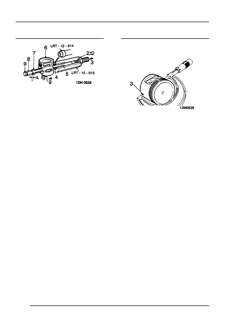
Pistons - remove
1. Clamp hexagon body of LRT-12-013 in vice.
2. Screw large nut back until flush with end of
centre screw.
3. Push centre screw forward until nut contacts
thrust race.
4. Locate piston adapter LRT-12-014 with its long
spigot inside bore of hexagon body.
5. Fit parallel sleeve, grooved end first, onto
centre screw and smear outside diameter with
engine oil.
6. Locate piston and connecting rod assembly on
centre screw and up to adapter LRT-12-014.
7. Fit remover/replacer bush of LRT-12-014 on
centre screw with flanged end away from
gudgeon pin.
8. Screw stop nut onto centre screw leaving
clearance A, between nut and
remover/replacer bush.
Clearance A = 3 mm.
9. Lock the stop nut securely with lockscrew.
10. Push connecting rod to right to locate end of
gudgeon pin in adapter LRT-12-014.
11. Ensure remover/replacer is located in gudgeon
pin bore of piston.
12. Screw large nut up to thrust race.
13. Hold lockscrew and turn large nut until
gudgeon pin is withdrawn from piston.
14. Dismantle tool and remove piston, connecting
rod and gudgeon pin.
15. Repeat above operation for remaining pistons.
Pistons - inspection
1. Clean carbon from pistons
2. Inspect pistons for distortion and cracks.
3. Measure piston diameter at 90
°
to gudgeon pin
axis and 8 mm from bottom of skirt. The piston
must be 0.018 mm to 0.033 mm smaller than
cylinder bore.
ENGINE
OVERHAUL
23
Cylinder bore - inspection
1. Measure cylinder bore wear in two axis 40 to
50 mm from top of bore.
Piston to cylinder bore clearance = 0.018 to
0.033 mm.
NOTE: Pistons are available in service
standard size and 0.508 mm oversize.
Service standard size pistons are supplied
0.0254 mm oversize. When fitting new service
standard size pistons, check for correct piston to
bore clearance, hone bore if necessary.
CAUTION: The temperature of piston and
cylinder block must be the same to ensure
accurate measurement. When reboring
cylinder block, the crankshaft main bearing caps
must be fitted and bolts tighten to correct
torque.
2. If only new piston rings are to be fitted, break
cylinder bore glazing using a fine grit, to
produce a 60
°
cross-hatch finish.
CAUTION: Ensure all traces of grit are
removed after above operation.
Connecting rod - inspection
1. Check alignment of connecting rod.
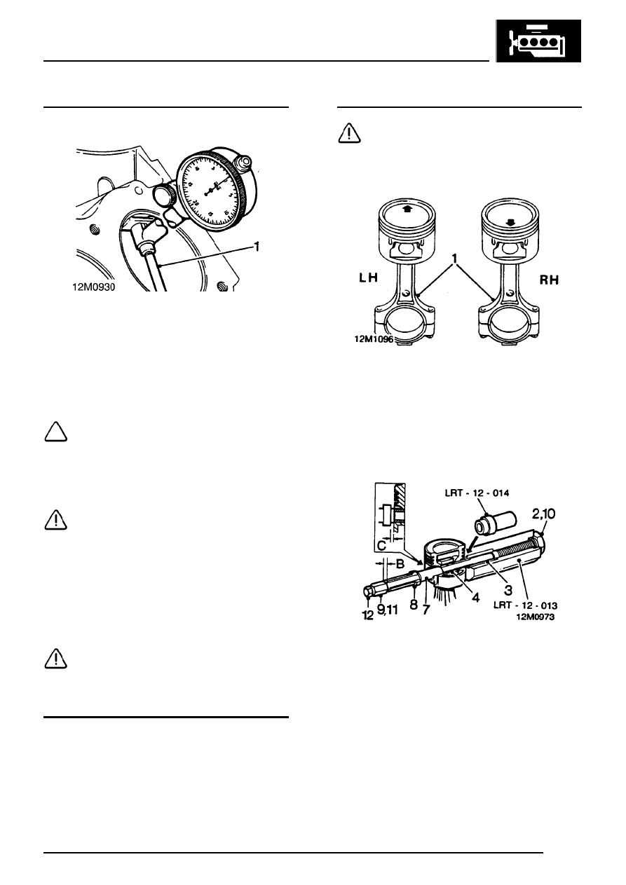
Pistons - refit
CAUTION: On later 4.2L engines the piston
has a 0.5 mm offset gudgeon pin which
can be identified by an arrow mark on the
piston crown. This arrow MUST always point to
the front of the engine.
1.
4.2L engine only: Assemble pistons to
connecting rods with arrow on piston pointing
towards domed shaped boss on connecting
rod for RH bank of cylinders, and arrow
pointing away from dome shaped boss for LH
bank of cylinders.
2. Clamp hexagon body of LRT-12-013 in vice.
3. Remove large nut and pull the centre screw 50
mm out of hexagon body.
4. Locate piston adapter LRT-12-014 with its long
spigot inside bore of hexagon body.
5. Fit parallel sleeve, grooved end last, up to
shoulder on centre screw.
6. Lubricate gudgeon pin and bores of connecting
rod and piston with graphited oil.
7. Locate connecting rod and piston to centre
screw with connecting rod entered on sleeve
up to groove.
ENGINE
24
OVERHAUL
8. Fit gudgeon pin onto centre screw and into
piston bore up to connecting rod.
9. Fit remover/replacer bush with flanged end
towards gudgeon pin.
10. Screw the stop nut onto centre screw and
position piston against face of adaptor
LRT-12-014.
11. Lubricate centre screw threads and thrust race
with graphited oil, fit, and screw large nut up to
thrust race.
12. Adjust stop nut leaving clearance B, between
nut and remover/replacer bush.
Clearance B = 0.8 mm.
13. Lock the stop nut securely with lockscrew.
14. Set torque wrench to 16 Nm, and using socket
on large nut, pull gudgeon pin in until flange of
remover/replacer bush is distance C from face
of piston.
Distance C = 4 mm.
CAUTION: Flange of remover/replacer
must not be allowed to contact piston. If
torque figure is not achieved during above
operation, fit of gudgeon pin to connecting rod is
not acceptable and necessitates renewal of
components. The centre screw and thrust race
must be kept well lubricated throughout
operation.
15. Dismantle tool, remove piston, check no
damage has occurred during pressing and
piston moves freely on gudgeon pin.
16. Repeat above operation for remaining pistons.
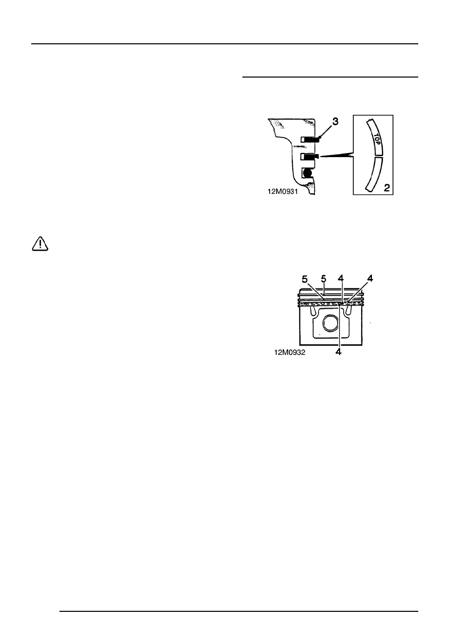
Pistons and connecting rods - refit
1. Fit oil control ring rails and expander, ensuring
ends butt and not overlap.
2. Fit ring marked ’TOP’ with marking uppermost
into second groove.
3. Fit top compression ring into groove either way
round.
4. Position oil control expander ring joint and ring
rail gaps all at one side, between gudgeon pin
and piston thrust face. Space gaps in ring rails
approximately 25 mm each side of expander
ring joint.
5. Position compression rings with ring gaps on
opposite sides of piston between gudgeon pin
and piston thrust face.
6. Fit big-end bearing shell to connecting rod.
7. Lubricate big-end bearing shell, piston rings
and gudgeon pin with engine oil.
8. Lubricate cylinder bores and crankshaft
big-end journals with engine oil.
ENGINE
OVERHAUL
25
9. Fit ring clamp to piston and compress piston
rings.
10. Fit plastic tubing to connecting rod bolts.
11. Insert connecting rod and piston assembly into
respective cylinder bore ensuring domed
shaped boss on connecting rod faces towards
front of engine on RH bank of cylinders, and
towards rear on LH bank of cylinders.
NOTE: When both connecting rods are
fitted to each journal, bosses will face
towards each other.
12. Pull connecting rod on to crankshaft journal.
CAUTION: Take care not to scratch
crankshaft journals.
13. Fit big-end bearing caps and bearing shells.
14. Fit cylinder head(s).
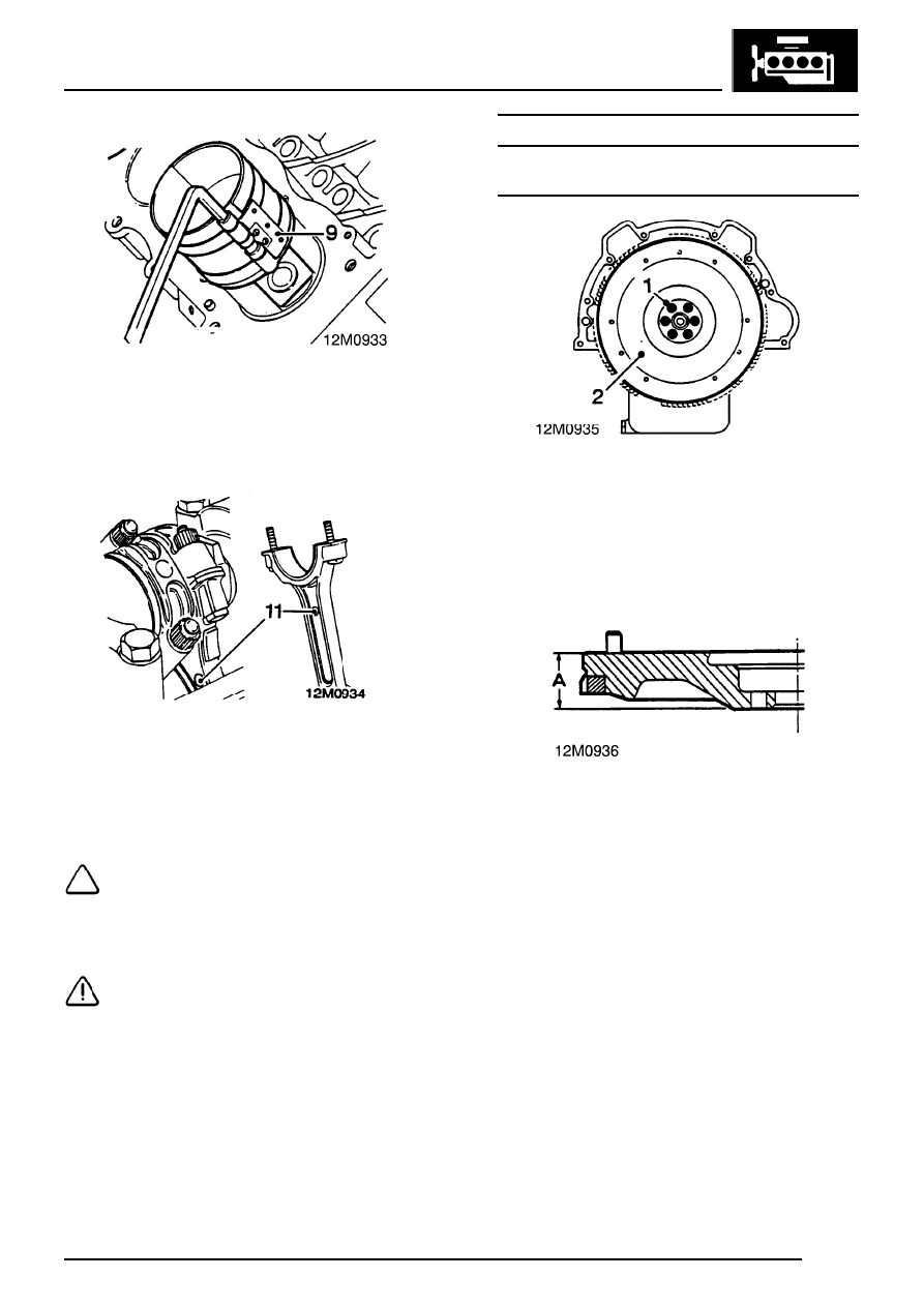
FLYWHEEL
Flywheel- remove
1. Restrain crankshaft and remove 6 bolts
securing flywheel.
2. Remove flywheel.
Inspect
1. Inspect flywheel face for cracks, scores and
overheating. The flywheel can be refaced
providing thickness does not go below
minimum.
Flywheel minimum thickness A = 39.93 mm
2. Inspect ring gear for worn, chipped and broken
teeth.
3. Renew ring gear if necessary.
Нет комментариевНе стесняйтесь поделиться с нами вашим ценным мнением.
Текст