Land Rover V8 engine. Manual — part 3
ENGINE
6
DESCRIPTION AND OPERATION
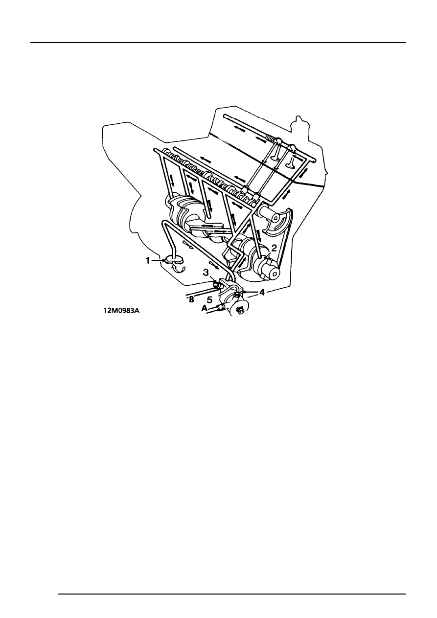
Lubrication - Engine numbers without suffix B
1. Oil strainer
2. Crankshaft main bearing oil feed
3. Oil pressure relief valve
4. Oil pump
5. Main gallery
A Oil to cooler
B Oil from cooler
ENGINE
DESCRIPTION AND OPERATION
7
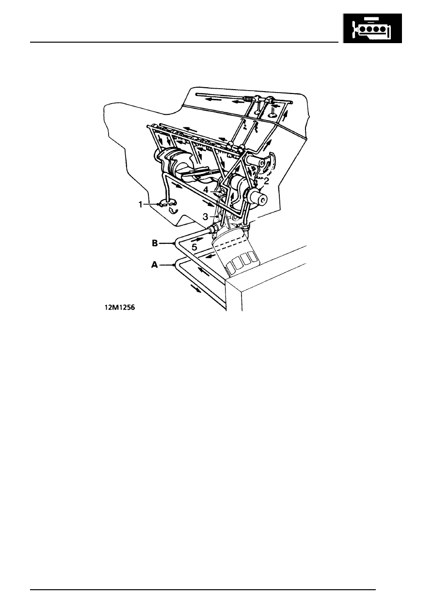
Lubrication - Engine numbers with suffix B
1. Oil strainer
2. Oil pump
3. Pressure relief valve
4. Oil pressure switch
5. Main gallery
A Oil to cooler
B Oil from cooler
Engine numbers without suffix B
The full flow lubrication system uses an external
gear pump which is driven by the distributor drive
shaft. The oil pump gears are housed in the timing
cover and the oil pressure relief valve and warning
light switch are fitted to the oil pump cover.
Engine numbers with suffix B
The full flow lubrication system uses a gear type oil
pump driven from the crankshaft. The assembly is
integral with the timing cover which also carries the
full flow oil filter, oil pressure switch and pressure
relief valve.
All engines
Oil is drawn from the pressed steel sump through a
strainer and into the oil pump, excess pressure
being relieved by the pressure relief valve. The oil
pressure warning light switch is screwed into the oil
pump cover and registers the oil pressure in the
main oil gallery on the outflow side of the filter.
Pressurised oil passes through an oil cooler - if fitted
to the full flow oil filter and to internal drillings in the
crankshaft where it is directed to each main bearing
and to the big end bearings via Nos. 1, 3 and 5 main
bearings. An internal drilling in the cylinder block
directs oil to the camshaft where it passes through
further internal drillings to the hydraulic tappets,
camshaft journals and rocker shaft. Lubrication to
the thrust side of the cylinders is by oil grooves
machined in each connecting rod big end joint face,
which are timed to align with holes in the big end
journals on the power and exhaust strokes.
ENGINE
8
DESCRIPTION AND OPERATION
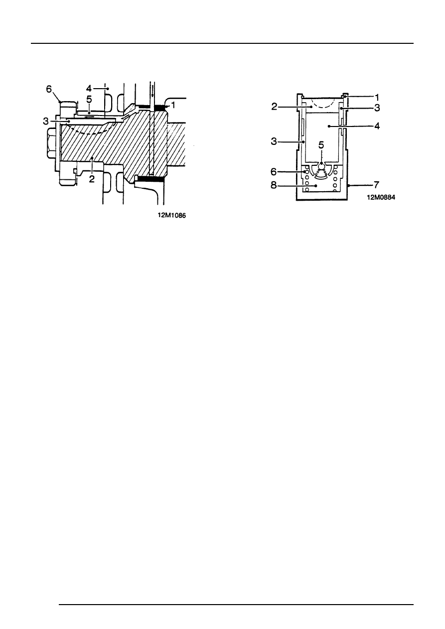
Distributor drive and timing chain lubrication
1. Bearing
2. Camshaft
3. Key
4. Camshaft timing chain sprocket
5. Spacer
6. Distributor drive gear
The distributor drive and timing chain are lubricated
from the camshaft front bearing. The feed to the
timing chain is channelled along the camshaft
sprocket, key and spacer.
Hydraulic tappets
1. Clip
2. Pushrod seat
3. Inner sleeve
4. Upper chamber
5. Non-return ball valve
6. Spring
7. Outer sleeve
8. Lower chamber - high pressure
The purpose of the hydraulic tappet is to provide
maintenance free and quiet operation of the inlet
and exhaust valves. It achieves this by utilising
engine oil pressure to eliminate the mechanical
clearance between the rockers and the valve stems.
During normal operation, engine oil pressure present
in the upper chamber passes through the non-return
ball valve and into the lower, high pressure,
chamber.
When the cam begins to lift the outer sleeve, the
resistance of the valve spring felt through the push
rod and seat causes the tappet inner sleeve to move
downwards inside the outer sleeve. This downward
movement of the inner sleeve closes the ball valve
and increases the pressure in the lower, high
pressure chamber, sufficiently to ensure that the
push rod opens the valve fully.
As the tappet moves off the peak of the cam the ball
valve opens to equalise the pressure in both
chambers which ensures the valve closes when the
tappet is on the back of the cam.
ENGINE
OVERHAUL
1
ROCKER SHAFTS
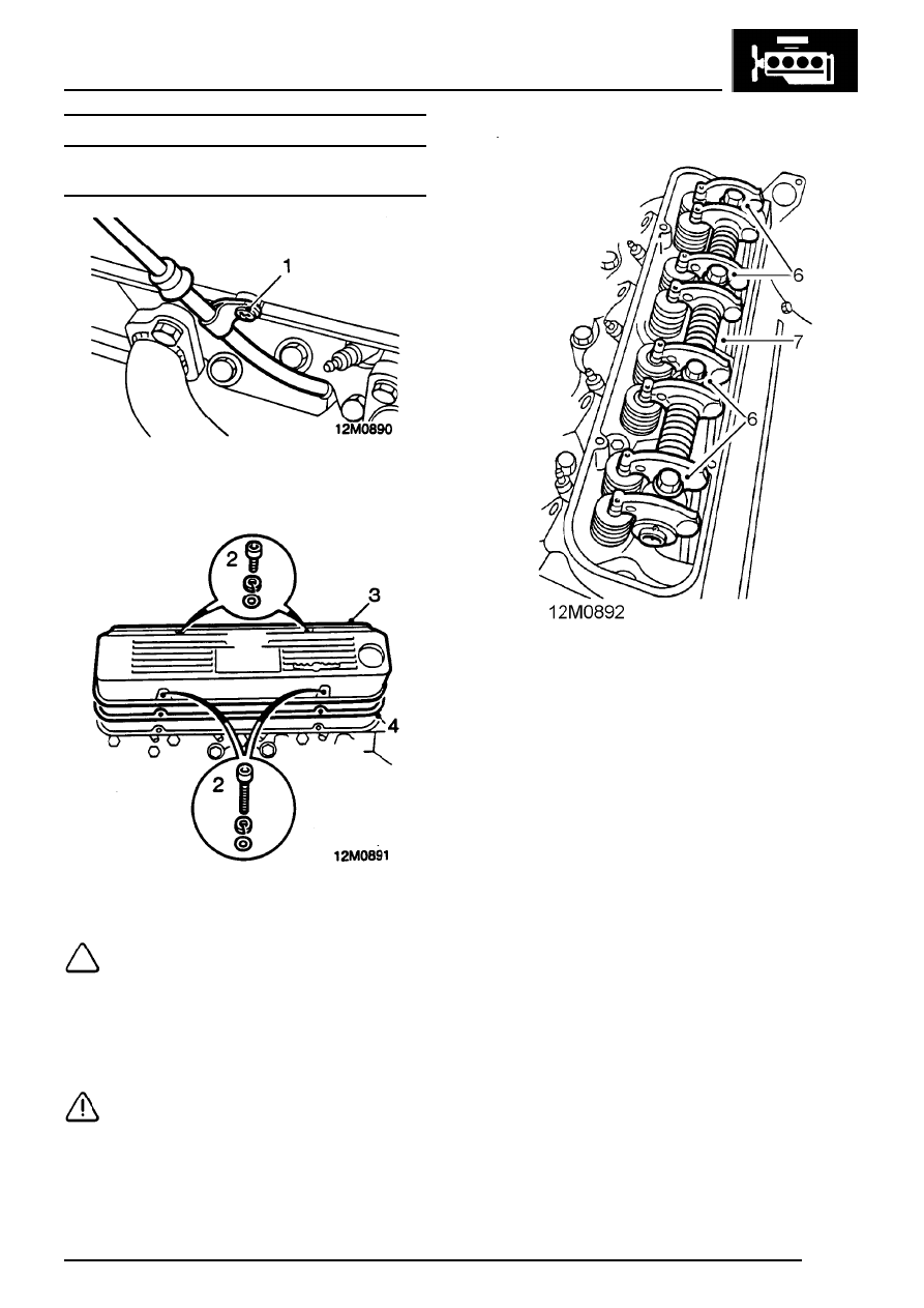
Rocker shaft - remove
1. LH rocker shaft only: Remove screw securing
dipstick tube to rocker cover.
2. Remove 4 screws securing rocker cover to
cylinder head.
NOTE: Mark position of 2 longer screws.
3. Remove rocker cover.
4. Remove and discard gasket from rocker cover.
5. Mark each rocker shaft in relation to original
cylinder head.
CAUTION: Incorrect fitment of rocker
shafts will lead to an oil feed restriction.
6. Progressively slacken and remove 4 bolts
securing rocker shaft assembly to cylinder
head.
7. Remove rocker shaft assembly.
8. Remove pushrods and store in fitted order.
Нет комментариевНе стесняйтесь поделиться с нами вашим ценным мнением.
Текст