Defender (1993+). Manual — part 7
GENERAL FITTING INSTRUCTIONS
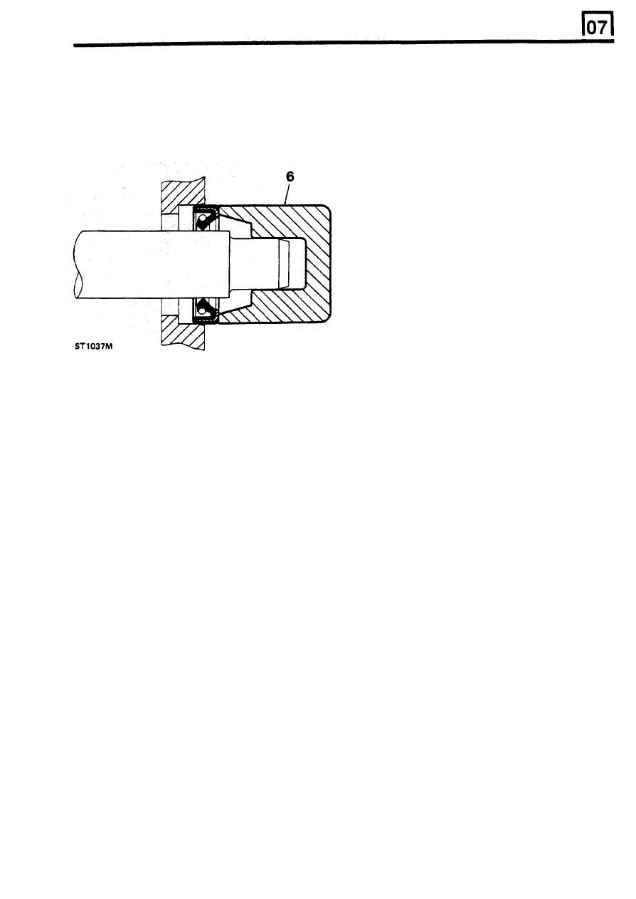
6.
Grease outside diameter of seal, place square
to housing recess and press into position,
using great care and
if
possible a 'bell piece'
1.
Before removing any brake or power steering
to ensure that seal is not tilted. (In some
hose, clean end fittings and area surrounding
cases
it
may be preferable to fit seal to
them as thoroughly as possible.
housing before fitting to shaft.) Never let
2. Obtain
appropriate blanking caps before
weight of unsupported shaft rest in seal.
detaching hose end fittings,
so that ports can
be immediately covered to exclude dirt.
3.
Clean hose externally and blow through
with
airline,
Examine
carefully
for
cracks,
separation of plies, security of end fittings and
external damage.
Reject
any hose found
faulty.
4.
When
refitting
hose,
ensure
that
no
unnecessary bends are introduced, and that
hose is not twisted before
or
during tightening
of union nuts.
5.
Containers
for
hydraulic fluid must be kept
absolutely clean.
6.
Do not store hydraulic fluid in an unsealed
container.
It
will absorb water, and fluid in this
condition would be dangerous
to
use due to a
lowering
of its boiling point.
7.
Do
not
allow
hydraulic
fluid
to
be
7.
If
correct service tool is not available, use a
contaminated
with
mineral oil, or use a
suitable drift approximately
0,4
mm smaller
container which has previously contained
than outside diameter of seal. Use a hammer
mineral oil.
VERY GENTLY on drift
if
a press is not
8.
Do not re-use fluid bled from system.
suitable.
9.
Always use clean brake fluid to clean
8.
Press or drift seal in
to
depth of housing
if
hydraulic components.
housing
is
shouldered,
or flush with face of
10.
Fit a blanking cap to a hydraulic union and a
housing where no shoulder is provided.
plug
to
its socket after removal
to
prevent
Ensure that the seal does not enter the
ingress of dirt.
housing
in a tilted position.
11.
Absolute cleanliness must be observed
with
hydraulic components at all times.
NOTE: Most cases of failure or leakage of
12.
After any work on hydraulic systems, inspect
oil seals are due to careless fitting, and
carefully for leaks underneath the vehicle
resulting damage to both seals and sealing
while a second operator applies maximum
surfaces. Care in fitting is essential if good
pressure
to
the brakes (engine running) and
results are to be obtained.
operates the steering.
FLEXIBLE HYDRAULIC
PIPES, HOSES
JOINTS AND
JOINT FACES
1.
Always use correct gaskets where they are
specified.
2. Use
jointing
compound
only
when
recommended. Otherwise fit joints dry.
3.
When jointing compound is used, apply in a
thin uniform film to metal surfaces; take great
care to prevent
it
from entering oilways, pipes
or blind tapped holes.
4.
Remove all traces of old jointing materials
prior to reassembly.
Do
not use a tool which
could damage joint faces.
5.
Inspect joint faces for scratches or burrs and
remove with a fine file
or oil stone; do not
allow swarf or dirt to enter tapped holes or
enclosed parts.
6.
Blow out any pipes, channels or crevices with
compressed air, renewing any O-rings or
seals displaced by air blast.
REISSUED: FEB
1993
3
GENERAL FITTING INSTRUCTIONS
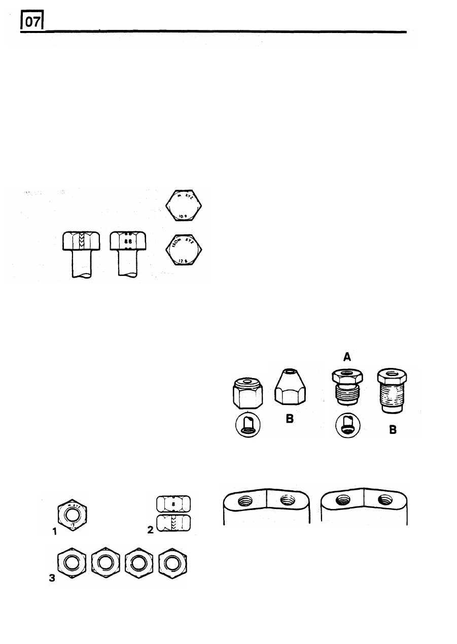
METRIC
BOLT IDENTIFICATION HYDRAULIC FlTTlNGS - Metrication
1.
An IS0 metric bolt or screw, made of steel
WARNING: Metric and Unified threaded hydraulic
and larger than
6
mm in diameter can be
parts. Although pipe connections t o brake
identified by either of the symbols IS0 M or
M
system units incorporate threads of metric form,
embossed or indented on top of the head.
those for power assisted steering are of UNF
2. In addition to marks
to identify the
type. I t is vitally important that these two thread
manufacture, the head is also marked with
forms are not confused, and careful study should
symbols
to
indicate the strength grade e.g.
be made of the following notes.
8.8, 10.9,
12.9
or 14.9, where the first figure
gives the minimum tensile strength of the bolt
Metric threads and metric sizes are being introduced
material in tns of kg/sq mm.
into motor vehicle manufacture and some duplication
Zinc plated IS0 metric bolts and nuts are
of parts must be expected. Although standardisation
chromate passivated, a greenish-khaki to
must in the long run be good, it would be wrong not
to give warning cf the dangers that exist while UNF
and metric threaded hydraulic parts continue
together in service. Fitting UNF pipe nuts into metric
ports and vice-versa should not happen, but
experience of the change from BSF to UNF indicated
that there is no certainty in relying upon the
difference in thread size when safety is involved.
To provide permanent identification of metric parts is
not easy but recognition has been assisted by the
following means. (Illustration A Metric,
B Unified.)
1. All metric pipe nuts, hose ends, unions and
bleed screws are coloured black.
2. The hexagon area
of pipe nuts is indented
with the letter
’M’.
3.
Metric and
UNF pipe nuts are slightly different
in shape.
gold-bronze colour.
ST1035M
METRIC NUT IDENTIFlCATlON
1.
A nut with an IS0 metric thread is marked on
one face or on one of the flats of the hexagon
with
the strength grade symbol
8, 12 or 14.
Some nuts with a strength 4,
5
or
6 are also
marked and some have the metric symbol
M
on the flat opposite the strength grade
marking.
2.
A clock face system is used as an alternative
method of indicating the strength grade. The
external chamfers or a face
of
the nut is
marked in a position relative to the
appropriate hour mark on a clock face to
indicate the strength grade.
3. A dot is used to locate the 12 o’clock position
and a dash
to
indicate the strength grade.
If
the grade is above 12,
two
dots identify the
12
o’clock position.
ST1034M
The metric female nut is always used
with
a trumpet
flared pipe and the metric male nut is always
used
with a convex flared pipe.
STt036M
4
REISSUED: FEB 1993
A
ST1033M
A
B
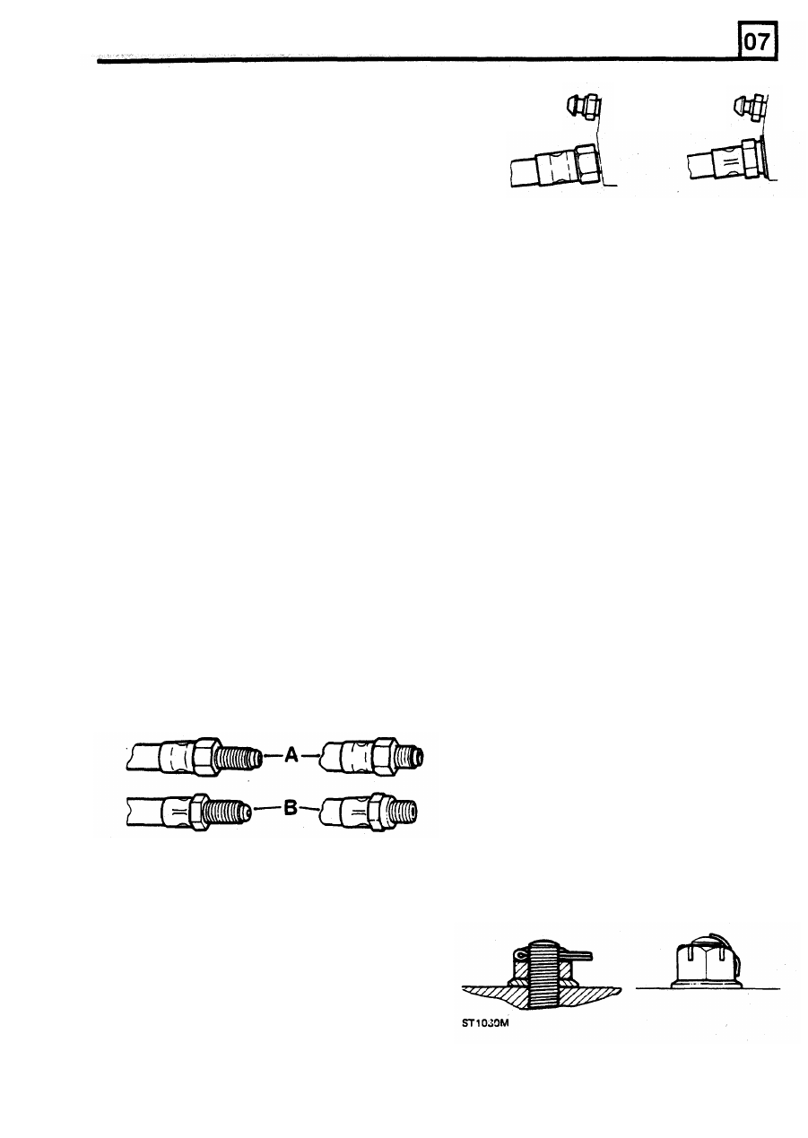
ST1031M
GENERAL FITTING INSTRUCTIONS
A
B
ST1032M
4. All metric ports in Cylinders and calipers have
no counterbores, but unfortunately a few
cylinders with UNF threads also have no
counterbore. The situation is, all ports with
counterbores are UNF,
but ports not
counterbored are most likely to be metric.
5. The coulour of the protective plugs in hydraulic
ports indicate the size and the type of the
threads but the function of the plugs is
protective and not designed
as
positive
identification. In production it is difficult to use
The greatest danger lies with the confusion of 10
the wrong plug but human error must be
mm and 3/8 in UNF pipe nuts used for 3/16 in (or
taken into account. The Plug colours and
4,751 mm) pipe. The 3/8 in UNF pipe nut or hose can
be screwed into a 10 mm port but is very slack and
easily stripped. The thread engagement is very weak
and cannot provide an adequate seal.
The opposite condition, a 10 mm nut in a 3/8 in port,
is difficult and unlikely to cause trouble. The 10 mm
nut will screw in 1 1/2 or 2 turns and seize. It has a
crossed thread 'feel' and it is impossible to force the
nut far enough to seal the pipe. With female pipe
nuts the position is of course reversed.
The other combinations are so different that there is
no danger of confusion.
KEYS AND KEYWAYS
thread sizes are:
RED
GREEN
YELLOW
PINK
BLACK
10 x 1 mm
GREY
12 x 1 mm
BROWN
14
x
1,5 mm
6.
Hose ends differ slightly between metric and
UNF. Gaskets are not used with metric hoses.
The UNF hose is sealed on the cylinder or
caliper face by a copper gasket by the metric
1.
Remove burrs from edges
of
keyways with a
hose seals against the bottom of the port and
fine
file
and
clean' thoroughly before
there is a gap between faces
of the hose and
attempting to refit key.
cylinder.
2. Clean and inspect key closely; keys are
Pipe sizes for UNF are 3/16
in, 1/4 in and 5/16 in
suitable for refitting only
if
indistinguishable
outside diameter.
from new, as any indentation may indicate the
Metric pipe sizes are
4,75
mm, 6 mm and 8 mm.
onset of wear.
4,75 mm pipe is exactly the same as 3/16 in pipe.
6
mm pipe is 0.014 in smaller than 1/4 in pipe. 8 mm
pipe is
0.002 in
larger than 5/16
in
pipe.
Convex pipe flares are shaped differently for metric
sizes and when making pipes for metric equipment,
metric pipe flaring tools must
be used.
UNF
3/8 in
x
24 UNF
7/16 in
x
20 UNF
1/2 in
x 20 UNF
7/8 in
x
18 UNF
METRIC
TAB WASHERS
1.
Fit new washers in all places where they are
used. Always renew a used tab washer.
2. Ensure that the new tab washer is
of the
same design as that replaced.
SPLIT
PINS
1.
Fit new split pins throughout when replacing
any unit.
2. Always fit split pins where split pins were
originally used.
Do not substitute spring
washers: there is always a good reason for
the use of a split pin.
3.
All
split pins should be fitted as shown unless
otherwise stated.
REISSUED:
FEB 1993
5

GENERAL FlTTlNG INSTRUCTIONS
1
ST1039M
2
3
NUTS
UNIFIED THREAD IDENTIFICATION
1.
When tightening
a
slotted or castellated nut
1.
Bolts
never slacken it back to insert split pin or
A
circular recess is stamped in the upper
locking wire except in those recommended
surface of the bolt head.
cases where this forms part of an adjustment.
2. Nuts
If
difficulty
is
experienced, alternative washers
A continuous line of circles is indented
on
one
or nuts should
be selected, or washer
of the flats of the hexagon, parallel to the axis
thickness reduced.
of the nut.
is advisable to replace them with new ones of
The component is reduced
to
the core
the same type.
NOTE: Where bearing pre-load i s involved
nuts should be tightened i n accordance
with special instructions.
2. Where self-locking nuts have been removed
it
3.
Studs, Brake
Rods.
etc.
diameter for a short length at its extremity.
LOCKING WIRE
1.
Fit new locking wire of the correct type for all
assemblies incorporating
it.
2.
Arrange wire
so
that its tension tends to
tighten the bolt heads, or nuts, to which it is
fitted.
SCREW THREADS
1.
Both UNF and Metric threads to ISO
standards are used. See below for thread
identification.
2.
Damaged threads must always
be discarded.
Cleaning up threads with a die
or tap impairs
the strength and closeness of fit of the
threads and is not recommended.
3.
Always ensure that replacement bolts are at
least equal in strength
to
those replaced.
4.
Do not allow oil, grease or jointing compound
to
enter blind threaded holes.
The hydraulic
action on screwing
in the bolt or stud could
split the housing.
5. Always tighten a nut or bolt
to the
recommended torque figure. Damaged
or
corroded threads can affect the torque
reading.
6.
To
check or re-tighten a bolt
or
screw to a
specified torque figure, first slacken
a
quarter
of a turn, then re-tighten to the correct figure.
7. Always oil thread lightly before tightening to
ensure a free running thread, except in the
case of self-locking nuts.
6
REISSUED: FEB
1993
Нет комментариевНе стесняйтесь поделиться с нами вашим ценным мнением.
Текст