Defender (1993+). Manual — part 65
FRONT AXLE
AND FINAL DRIVE
29. Slacken off the adjusting nut until an end-play
OVERHAUL
STUB
AXLE,
AXLE
SHAFT,
30. Fit a new keyed lock tab washer.
ASSEMBLY
31. Fit and tighten the hub adjusting nut and
of
0,1270
to
0,1016
mm
is
obtained.
CONSTANT VELOCITY JOINT
AND SWIVEL
re-check the end-play before bending the lock
Special tool:
18G284AAH/LRT-37-004
bush
tab over.
extractor
32. Fit a new joint washer to the driving member
and fit the member
to
the hub and secure with
the five bolts tightening evenly to 60 to 70
33. Fit the original drive shaft shim and secure
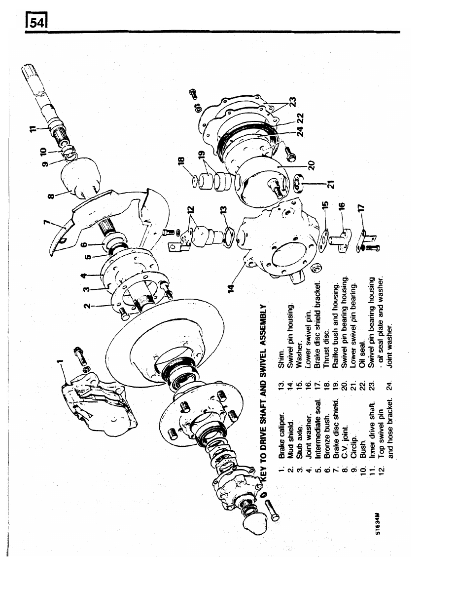
1.
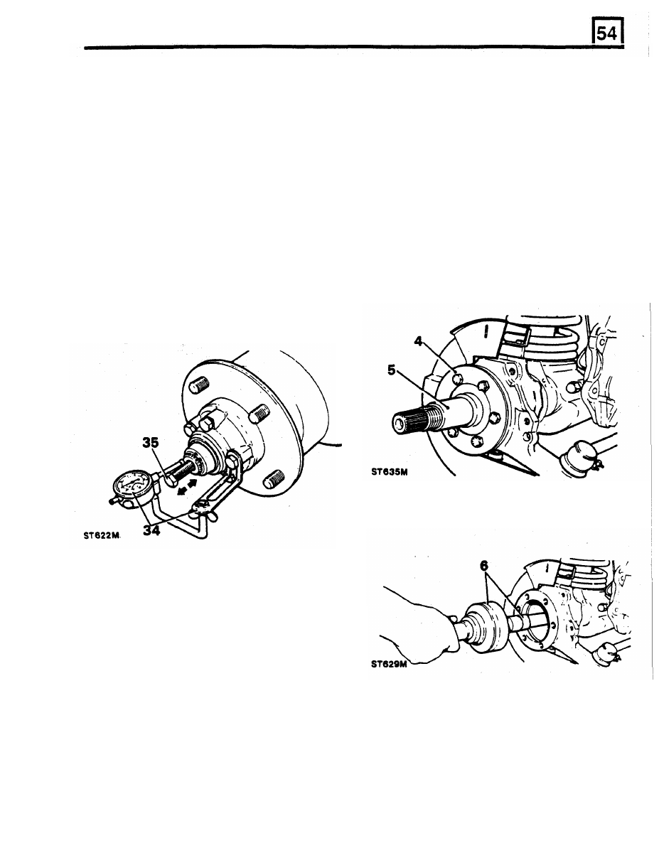
Remove the hub complete as described in the
operation to overhaul the hub assembly
34. To check the drive shaft end-play mount a dial
instructions
1
to
14.
guage using a bracket RO530106 and rest the
2. Drain the swivel pin housing and refit plug.
stylus in a loaded condition on the end of the
3. Remove the six bolts retaining the stub axle
to
the swivel housing.
35. Fit a suitable bolt to the threaded end
of
the
4.
Remove the mud shield.
5.
Remove the stub axle and joint washer.
Remove stub axle, axle shaft and constant
velocity joint
drive shaft and using a pair of pliers move the
drive shaft back and forth noting the dial
guage reading. The end-play should be
6.
Pull-out the axle shaft and constant velocity
joint from the axle casing.
36.
If
the end-play requires adjustment, remove
the circlip, measure the shim thickness and fit
an appropriate selective shim to give the
required end-play.
37. Remove the bolt
from
the drive shaft, fit the
circlip and dust cap.
38. Fit the brake caliper and tighten the two bolts
to the correct torque.
39.
Locate
the
jump
hose
in
the bracket and
tighten the locknuts or see caution below.
CAUTION:
If the jump nose was disconnected as
is
necessary
on
later vehicles the brake hydraulic
system must
be
bled.
40.
Fit the road wheel, remove the axle stand and
finally tighten the road wheel nuts.
41.
Operate the footbrake several times to locate
the brake pads before taking the vehicle on
the road.
Nm.
with the circlip.
drive shaft.
between 0,127 to 0,254 mm.
FRONT
AXLE AND FINAL DRIVE
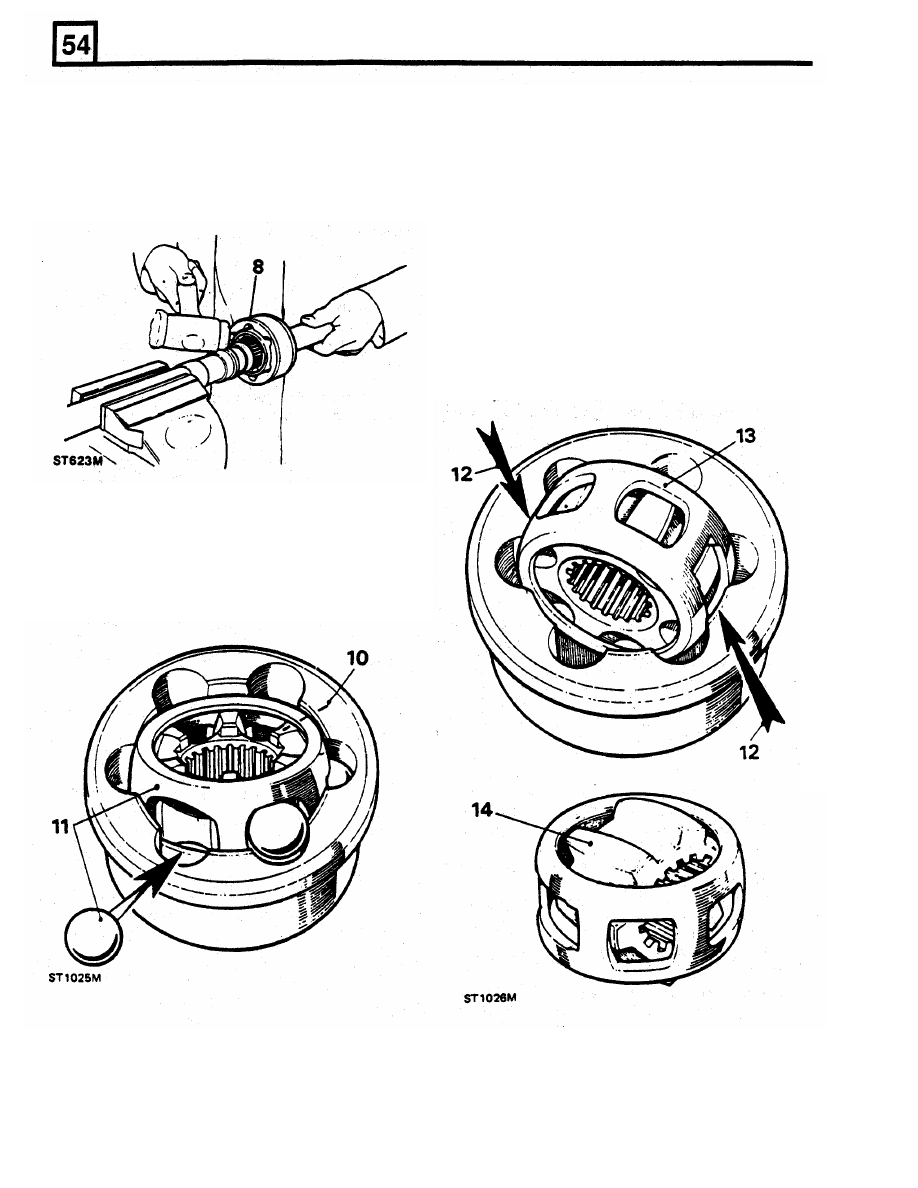
Remove constant velocity joint from axle shaft
12.
Swivel the cage into line with the axis of the
joint and turn it until two opposite windows
coincide with two lands of the joint housing.
7.
Hold the axle shaft firmly in a
soft
jawed vice
8.
Using
a
soft mallet drive the constant velocity
13.
Withdraw the cage.
joint from the shaft.
9.
Remove the circlip and collar from the axle
shaft.
14.
Turn the inner track at right angles to the
cage with
two
of the lands opposite the cage
openings and withdraw the inner race.
15.
Degrease and examine all components for
general wear and condition.
16.
Examine the inner and outer track, cage balls
and bearing surfaces of the constant velocity
joint for damage and excessive wear.
17.
To
assemble the constant velocity joint,
reverse the dismantling instructions and
lubricate with a recommended
EP
oil.
18.
Check that the end-float of the assembled
joint does not exceed 0,64 mm.
Dismantle the constant velocity joint
10.
Mark the relative positions
of
the constant
velocity joint inner and outer race and the
cage for correct reassembly.
11.
Tilt and swivel the cage and inner race
to
remove the balls.

FRONT AXLE
AND FINAL DRIVE
30.
Remove the top swivel pin retaining
bolts
complete with the brake jump hose bracket.
31.
Withdraw the top swivel pin and shims.
retrieving the lower taper bearing.
33. If the swivel
pin
housing
is
to
be renewed,
remove the drain and level plugs and
lock-stop bolt and nut.
Fit constant velocity joint t o axle
19.
Fit the collar and a new circlip.
20. Engage the constant velocity joint on the axle
32. Remove the swivel pin housing whilst
shaft splines and using a soft mallet, drive the
joint home.
Remove swivel pin bearing housing
34. Remove the seven bolts securing the swivel
pin bearing housing to the axle case and
remove the housing and joint washer.
35.
Remove and discard the swivel pin oil seal
and joint washer.
Overhaul swivel pin bearing housing
36. Prise-out the oil seal from the back
of
the
housing.
37. Drift-out the lower swivel pin bearing track.
21. To remove the bronze brush and oil seal use
38. Press-out the upper swivel pin in Railko bush
housing.
special tool 18G284AAH and
a
slide hammer.
Ensure that the fingers
of the tool locate
39. If worn, pitted or damaged, renew the
housing.
behind the bush, not the oil seal. Drive-out the
40.
Press-in the lower swivel pin bearing track.
bush, then extract the oil seal.
41. Press-in the Railko bush housing ensuring
that the machined flat is towards the back of
the housing, ie when the housing is fitted to
the axle, the flat faces inboard.
42. With the cavity side trailing press the axle
shaft oil seal into the housing and grease.
43. Fit the thrust disc into the bottom
of
the Railko
bush housing and check that
it
is
still
in
position when the swivel pin is fitted.
Renew stub axle intermediate oil seal and bush
Fit swivel p i n bearing housing t o axle
casing bolts with Loctite 270.
45.
Coat both sides
of
a joint washer and place in
position on the swivel pin bearing housing
to
axle mating face.
46.
Hang me swivel pin bearing housing oil seal,
retainer and joint washer over the back
of
the
47. Fit and secure the swivel pin bearing housing
to
the axle with the seven bolts tightening
evenly to 65
to 80
Nm.
22. Lubricate the seal and lip with EP 90 oil and
44. Coat the
swivel
pin bearing housing to axle
with the cavity side leading press-in a new
intermediate oil seal using
a
suitable tube.
23. Using a suitable block, press or drive-in the
bush up
to
the shoulder.
Remove swivel p i n housing
24. Remove the brake disc shield secured by one
housing.
nut and bolt at the bottom front and one
single
bolt,
behind the shield, in the swivel
housing.
25. Disconnect the track-rod end ball joint from
the housing.
26. Disconnect the drag-link ball joint.
27.
Remove the seven
bolts
securing the swivel
pin housing
o
il
seal
and retaining plate and
joint washer and release the assembly from
the swivel pin housing. Note that whilst the
joint washer can be removed at this stage, the
oil
seal and retaining plate must remain until
the swivel pin bearing housing is removed.
28. Remove the two bolts, complete with the
brake disc shield bracket, securing the lower
swivel pin to the housing.
29. Withdraw the lower swivel pin and joint
Fit swivel pin housing
48. Grease and fit the lower swivel pin bearing to
the bearing housing.
49. Place the swivel pin housing in position over
the swivel in bearing housing.
FRONT AXLE AND FINAL
DRIVE
Нет комментариевНе стесняйтесь поделиться с нами вашим ценным мнением.
Текст