Defender (1993+). Manual — part 68
FRONT
AXLE AND
FINAL
DRIVE
INSPECTION
4.
Carefully examine the sun and planet gears
for wear on the teeth and the running surfaces
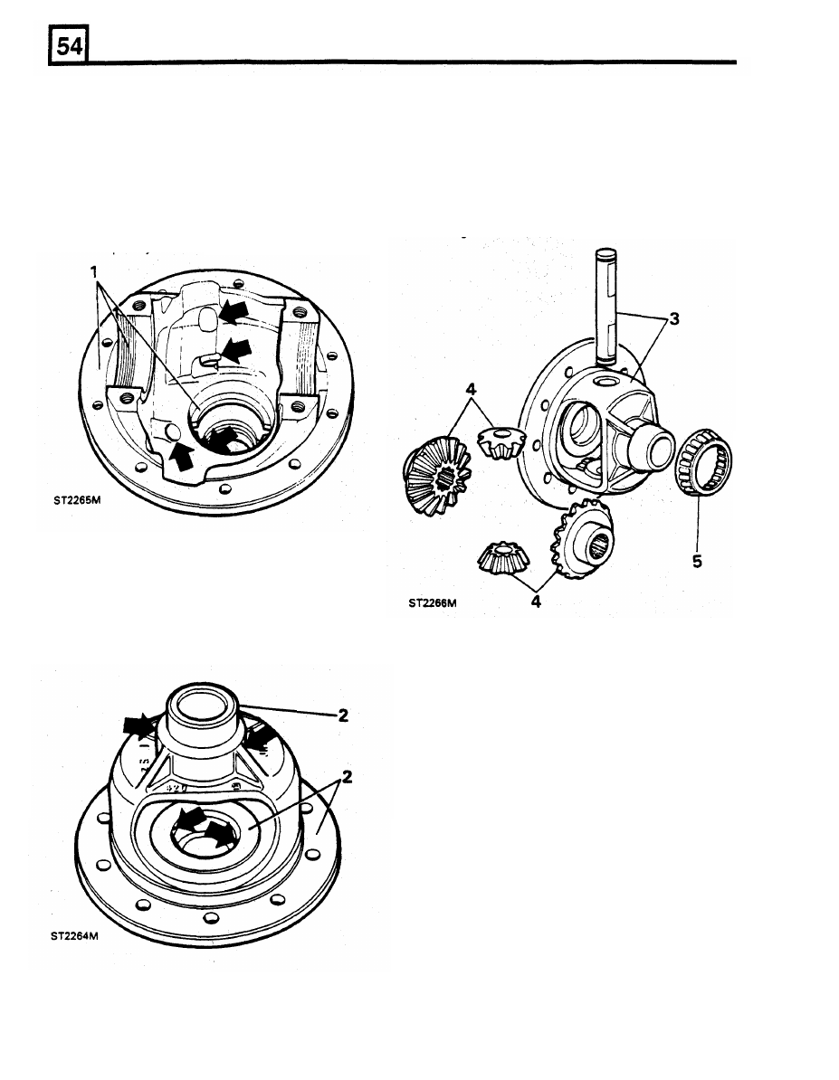
1.
Examine the pinion housing for damage.
in contact with the carrier. Check also for
Check the machined surfaces and remove any
signs of over heating.
burrs. Check the carrier bearing nut threads in
5.
Inspect all the bearings for wear, pitting, flats
the housing and caps and adjusting nuts for
on the rollers and overheating.
If
the bearings
damage and repair as necessary. Make sure
are serviceable they can be refitted but
if
new
that the cast-in lubrication passages (arrowed)
ones are available they must be renewed
including the passage
to the
tail bearing, are
together with the tracks.
completely clear of any obstruction.
2. Examine the machined surfaces of the
differential carrier for damage, pitting, scores
and wear and in particular the surfaces on
which the sun and planet gears run. Also,
ensure that the four
lubrication holes
(arrowed) are clear. Any obstruction here
could cause future bearing failure.
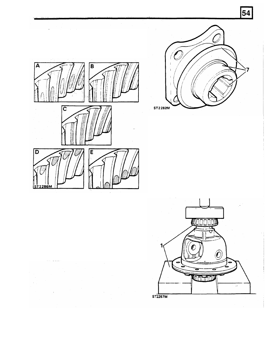
6.
Examine the crown wheel and pinion for
excessive and abnormal wear and signs of
over-heating. Compare the
tooth
contact on
the crown wheel driving side with the
examples illustrated below. These examples,
however, are for the rear axle crown wheel
where the pinion
is
driven clockwise. Tooth
contact for the front axle crown wheel, where
the pinion is driven anticlockwise, is the same
but on the opposite side
of
the
tooth. The first
example
" A " shows the marks that should be
made by a correctly meshed crown wheel and
pinion.
The
remaining examples
show
incorrect tooth contact.
3.
Check the cross shaft
for
scores and pitting.
Insert the shaft in the carrier to check for
excessive wear.
FRONT AXLE AND FINAL
DRIVE
A.
Correct contact.
B.
C.
D.
E.
Heel contact - Insufficient backlash.
Root contact - Pinion too far in mesh.
Peak contact - Pinion too far out of mesh.
Toe contact - Excessive backlash.
ASSEMBLE
Differential carrier and crown wheel
1.
Lubricate the carrier bearing journals with
clean oil and start the bearing squarely on to
one side of the carrier, largest diameter
towards the carrier.
It
does not matter which
bearing is fitted first. Mount the carrier
squarely under a suitable press, supporting
it
under the flange, as close as possible to the
journals. Slowly press the bearing fully home
against the carrier shoulder.
2. Repeat the above procedure
to
fit the second
bearing.
NOTE: The crown wheel and pinion are only
supplied as a matched set likewise the sun and
planet differential gears.
7.
Finally, check the condition
of the pinion and
driving flange splines and ensure that the
machined outer diameter
of the flange is free
from any damage that could destroy a new oil
seal. Check that the mud deflector is not
damaged or buckled
to
the extent that
it
cannot deflect mud and water away
from the
oil seal.
FRONT AXLE AND FINAL DRIVE
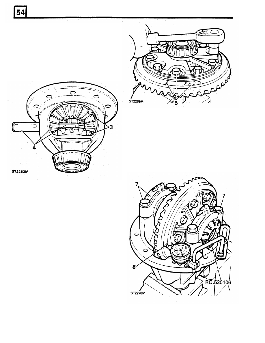
3.
Lubricate and
fit
the
two
sun gears followed
by the planet gears.
4.
Align the planet gears
with
the carrier holes
and
fit
the cross shaft. Secure the shaft with
new circlips. Check the gears for freedom of
rotation and that there are not tight spots.
Only nominal backlash should be present but
if
excessive, the gears or the carrier or both
should be changed since there is no provision
for adjustment.
6.
To check the crown wheel for run out, secure
the pinion housing in the vice in a vertical
position. Fit the tracks to the carrier bearings
and lower the assembly into the pinion
housing.
7.
Fit the bearing caps, lining up the marks and
just nip the bolts.
Do not fully tighten. Fit the
bearing adjuster nuts and tighten using
service tool
RO
530105
until there is no end
float between the bearings. Now, tighten the
bearing cap bolts evenly to the correct torque.
5. Check that the serial number etched on the
pinion end face is the same as that marked
on the crown wheel. Clean the crown wheel
and carrier mating faces and check that there
are
no
burrs or any other damage that could
cause excessive run-out
of the crown wheel. If
the
original crown wheel and pinion is being
refitted ensure that the marks made when
dismantling line up. Since the crown wheel is
a fairly tight fit on the carrier, the bolt holes
should be lined up first while locating the
crown wheel squarely on the carrier. Fit and
tighten the bolts evenly, a little at a time, until
the crown wheel has pulled down on
to the
carrier flange. Tighten the bolts temporarily
to
the correct torque.
FRONT
AXLE AND FINAL DRIVE
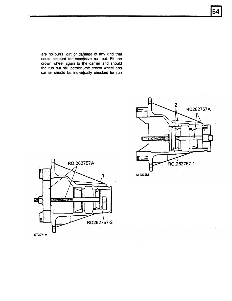
8.
Mount a dial test indicator on the flange of the
2. Fit the bearing head track and the original
pinion housing using bracket RO 530106 so
shim using main
tool RO 262757A and
that the stylus rests on the back of the crown
adaptor
RO 262757-1. Lubricate and start the
wheel. Turn the crown wheel and
if
the run
track squarely in the housing and assemble
out exceeds 0,10mm remove the crown wheel
the
tool
as shown below.
If
the shim was
from the carrier and check again that there
damaged during removal
fit
a new one
of the
same thickness.
If the
shim
was lost before
the size
was measured,
fit
a
replacement
shim at least 1,27mm
thick. Turn
the nut
slowly, using a
box spanner,
until the track is
fully home against
the housing
shoulder.
It
is
out on a lathe or similar equipment where the
vital to the successful
assembly
of the
parts can be accurately turned and measured.
differential and in particular the following
pinion height setting, that the track and shim
9.
When
satisfied
that
the run
out
is within the
specified limit,
remove
the crown wheel bolts,
one stud
at a
time,
coat
the
theads
with Loctite
Studlock
and refit the
bolts tightening evenly
1. To fit the pinion tail
bearing
track, lubricate
and start the track
squarely
in the pinion
housing. Assemble
the
special tool
RO
262757A and adaptor RO
262757-2
as
illustrated below. Slowly turn the nut clockwise
until
the
track
is fully
home against the
housing shoulder.
Pinion height setting
1.
Fit the pinion head bearing to the pinion with
press M.S. 47 and collets 18G 47-6 and 18G
47-6/2. Note that the smaller register on 18G
47-6/2 must be uppermost against the
bearing. Ensure that the larger diameter of the
bearing is towards the gear. Lubricate the
pinion and press it slowly on to the bearing.
to the correct torque.
Fitting pinion bearing tracks
is indeed pressed fully home.
Нет комментариевНе стесняйтесь поделиться с нами вашим ценным мнением.
Текст