Defender (1993+). Manual — part 16
ENGINE
RR3524M
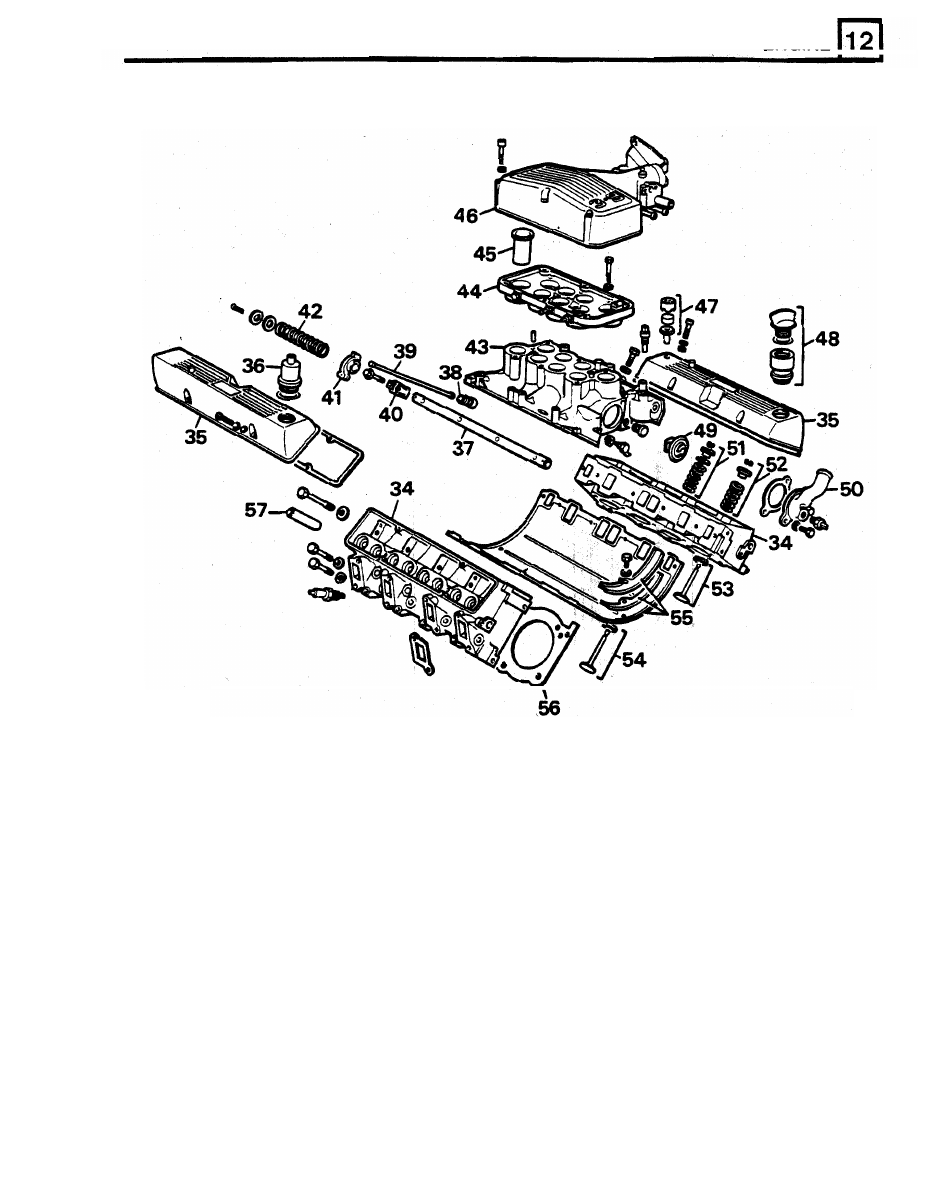
34. Cylinder heads (2)
46. Plenum chamber upper
35. Rocker covers (2)
47, Air filter
36. Oil separator
48. Oil filler
37. Rocker shafts (2)
49. Thermostat
38. Hydraulic tappets (8)
50. Thermostat cover
39. Pushrods (8)
51. Inlet valve spring, cap, seal
and
collets
(8)
40. Rocker brackets (8)
52. Exhaust valve spring, cap, collets
(8)
41. Rocker arms (4) left and
(4)
right
53. Inlet valve and seat (8)
42. Rocker shaft springs (6)
54. Exhaust valve and seat (8)
43. Inlet manifold
55. Tappet cover gasket and seals
44.
Plenum chamber lower
56. Cylinder head gaskets (2)
45. Ram pipes (8)
57. Valve guides (16)
ENGINE
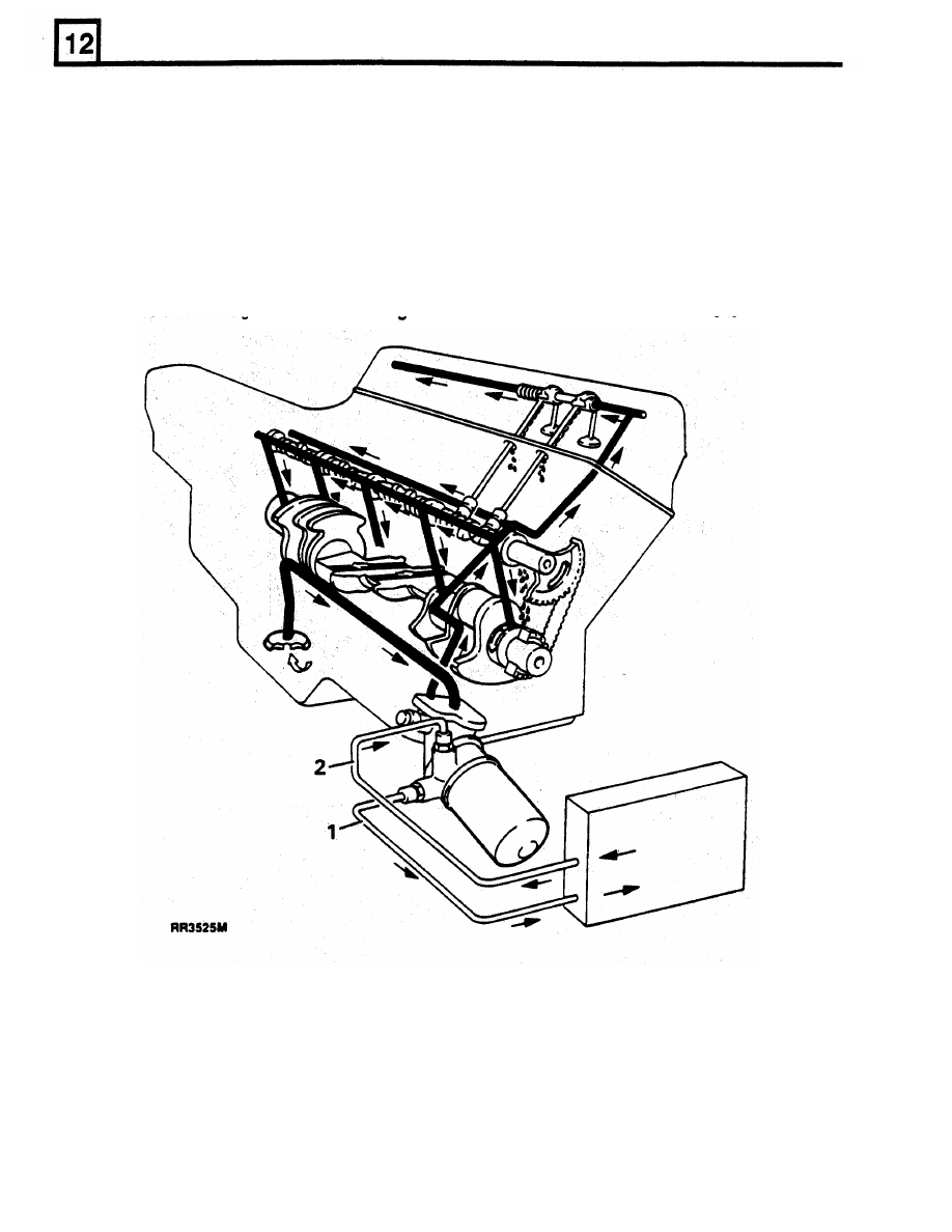
Lubrication
system
The
V8
full flow lubrication system uses an external gear pump which
is driven from the front of the camshaft
via the distributor drive shaft. The oil pump gears are housed in the timing cover and the pressure relief valve,
warning light switch and filter are
fitted
to the gear cover.
Oil drawn through the centrally located steel gauze strainer in the sump, is pumped under pressure through oil
cooler located
in the lower half of the main coolant radiator. The cooled oil then passes through the filter,
before being distributed from the main gallery via drillings, to the various components in the engine.
Lubrication to
the
thrust side of the cylinders
is
by
oil
grooves machined in each connecting rod big end joint
face, which are timed to align with holes in the big end journals on the Dower and exhaust strokes.
Lubrication system
1
Oil to cooler
2
Oil from cooler
ENGINE
RR3528M
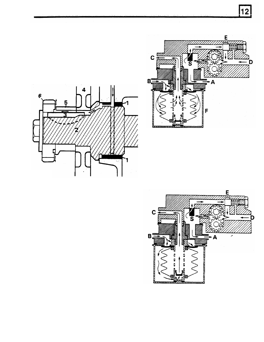
Distributor/oil pump drive and timing chain
lubrication
The distributor/oil pump drive, and timing chain
lubricated from the camshaft front bearing. The feed
to
the timing chain is channelled along the camshaft
sprocket, key and spacer where
it
sprays onto the
chain.
Unfiltered oil
Any blockage of the filter element will open the
by-pass valve and maintain an un-filtered
oil
supply
RR3526M
to
the bearings.
1
Bearing
2
Camshaft
3
Key
4
Cam
gear
5 Spacer
6
Distributor oil pump drive gear
Filtered oil
Lubrication pressure is controlled by the pressure
relief valve
E which allows excess pressure to
escape into the pump suction gallery D. The oil is
then pumped through the cooler via connections A
and
B before passing through the anti-siphon valve
and into the filter. Filtered oil
is
supplied to the
engine bearings by port
C.
F
RR3529M
ENGINE
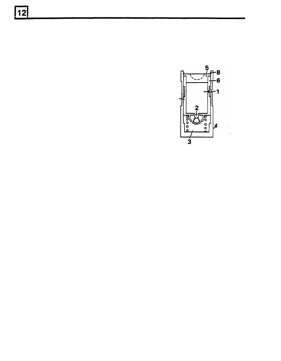
Hydraulic tappets
As the tappet assembly moves
off
the peak of the
cam
to
the closing side, the ball valve
2
opens
to
The purpose
of the hydraulic tappet is
to
provide
equalize the pressure in both chambers which
maintenance
free and quiet operation of the inlet and
ensures that the cylinder valve fully closes when the
exhaust valves. It achieves its designed purpose by
tappet
is on the back of the cam.
utilizing engine oil pressures to eliminate the
mechanical clearance between the rockers and the
valve stems.
Operation
During normal operation, engine oil pressure present
in the upper chamber
1,
passes through the
non-return ball valve
2
and into the lower (high
pressure) chamber 3.
When the cam begins
to
lift
the outer sleeve
4,
the
resistance
of the cylinder valve spring felt through
the push rod and seat 5, causes the inner sleeve
6,
to move downwards inside the outer. This slight
downward movement
of the inner sleeve
6,
closes
the ball valve
2
and increases the hydraulic pressure
in the high pressure chamber 3
,
sufficient
to ensure
that the push rod opens the cylinder valve fully.
RR3531M
1
Upperchamber
2 Non-return ball valve
3
Lower chamber (high pressure)
4
Outer sleeve
5 Pushrod seat
6
Inner sleeve
7
Spring
8
Clip
6
Нет комментариевНе стесняйтесь поделиться с нами вашим ценным мнением.
Текст