Discovery electrical Manual — part 25
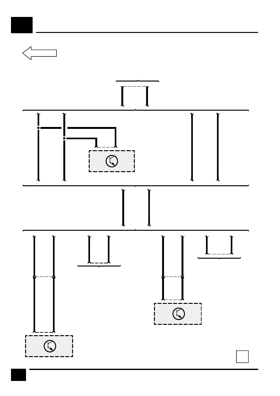
DATA LINK CONNECTOR
D3
2
CIRCUIT DIAGRAM
7
S2108
14
C217
WLG
With ABS
Z108
Anti–Lock Brake
System ECU
X318
Data Link Con-
nector (OBDII)
15
C2083
WK
WLG
WK
S2114
13
C2084
14
WLG
WK
Without ABS
With ABS
Without ABS
15
14
C217
Not used
Z132
Engine Control
Module (ECM)
27
C243
42
WLG
WK
15
300Tdi with EDC
MFI–T16
14
C217
15
MFI–V8
Not used
2
C1026
Z132
Engine Control
Module (ECM)
20
C1017
23
1
SFI–V8
300Tdi without
EDC
CIRCUIT OPERATION
Speedometer
The Vehicle Speed Sensor (X190) sends a signal to
the speedometer in the form of voltage pulses. The
pulses are filtered by a Vehicle Speed Sensor Buffer
inside the speedometer. The voltage alternates
between battery voltage and 0 volts 6 times per
wheel revolution. The speed sensor signal is also
sent to the Cruise Control ECU (Z121), Multifunction
Unit (MFU) (Z148) (Persian Gulf States), and the
Engine Control Module (Z132).
Tachometer
The tachometer displays engine speed in rpm.
Voltage pulses are taken from the Generator (Z106)
and are generated when the engine drive belt turns
the Generator pulley. The tachometer responds to
the frequency of the voltage pulses, which increases
proportionally to that of the engine speed.
Engine Coolant Temperature Gauge
The Engine Coolant Temperature Sensor (X114) has
approximately 136 ohms resistance when the coolant
temperature is low. As coolant temperature
increases, the resistance of the sensor decreases.
This varying resistance causes the current through
the sensor to change and the gauge to register the
temperature. When the coolant is hot, the resistance
of the sensor is approximately 17 ohms.
Fuel Gauge
When the fuel tank level is low, the resistance of the
fuel gauge sender is approximately 245 ohms. As the
fuel level increases, the resistance of the sender
decreases, causing the gauge to register the change.
When the fuel tank is full, the resistance of the sender
is approximately 19 ohms. When the fuel gauge
sender’
s resistance falls below approximately 25
ohms (6 liters/1.5 US gallons), the fuel warning light
will illuminate to warn the driver .
INSTRUMENTS
E1
1
CIRCUIT OPERATION

INSTRUMENTS
E1
2
CIRCUIT DIAGRAM
1
C370
See Fuse Details
See Fuse Details
15
C208
20
C204
3
C370
BR
2
C105
5
C209
2
C221
LG
S2049
S214
2
C222
P126
Fascia Fuse Box
X190
Vehicle Speed
Sensor
4
C221
YK
15
F 14
10 A
[1]
[12]
[11]
A
E1-3
S344
GY
1
B
S253
HJ8
See Ground Dis-
tribution
E201
17
C209
Instruments
Warnings and
Indicators
31
15
HJ9
Z142
Instrument
Cluster
[1]
Speedome-
ter
[11] Vehicle
Speed Input
[12] Vehicle
Speed Out-
put

INSTRUMENTS
E1
3
CIRCUIT DIAGRAM
A
E1-2
S2030
6
C243
Z132
Engine Control
Module (ECM)
29
C243
Z132
Engine Control
Module (ECM)
Not used
MFI–V8
300Tdi without
EDC
MFI–T16
300Tdi with EDC
12
C217
YK
Z132
Engine Control
Module (ECM)
11
C284
Z121
Cruise Control
ECU
27
C1017
HJ2
S2030
HJ2
Except NAS
NAS
YK
5
C1027
87
C2106
Z126
Service Re-
minder Unit
11
C284
Z121
Cruise Control
ECU
1
C2062
14
C205
Z148
Multi–Function
Unit (MFU)
Y
X241
Saudi Junction
Connector
1
C2062
Y
YK
Нет комментариевНе стесняйтесь поделиться с нами вашим ценным мнением.
Текст