Subaru Legacy (2022 year). Manual in english — page 18
(279,1)
position hold.
Hold last position function:
The angle of the reverse tilt-down mirror
can be set to the latest adjusted angle.
The hold last position function operates
when the following condition are met.
.
The memory function is not used.
.
The seat is moved forward or backward
1.18 in (30 mm) or more.
NOTE
.
The factory setting (default setting)
for this function is set as “non-opera-
tional”. This setting can be changed to
“operational” at SUBARU dealers. For
more details, contact a SUBARU dealer.
.
If the hold last position function
setting is “non-operation”, the reverse
tilt-down will move to the factory de-
fault position.
!
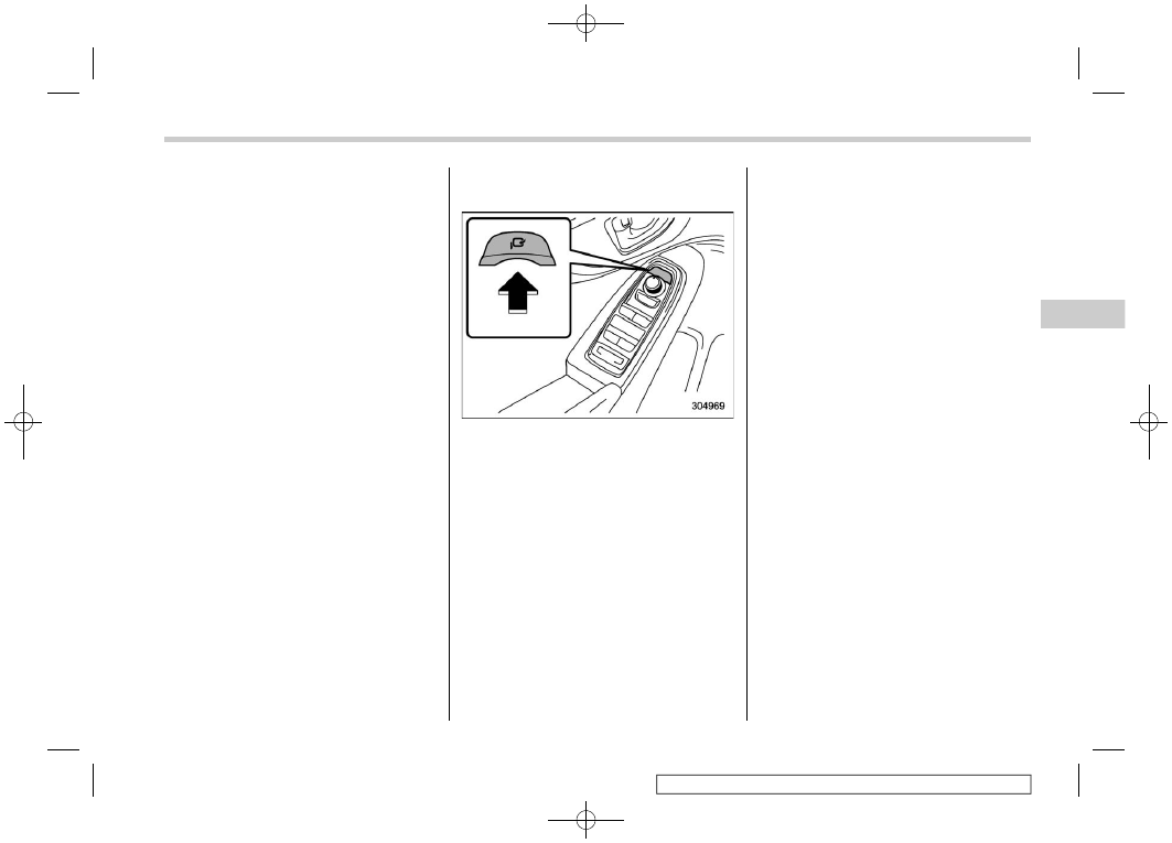
Power folding mirror switch (if
equipped)
The power folding mirror switch operates
when the ignition switch is in the “ON” or
“ACC” position.
To fold the outside mirrors, press the
power folding mirror switch. To unfold the
mirrors, press the switch again.
NOTE
.
If the outside mirrors have been
operated (folded or unfolded) manually,
when you turn the ignition switch from
the “LOCK”/“OFF” position to the
“ACC” or “ON” position, the outside
mirrors may be adjusted automatically
depending on the status of the power
folding mirror switch.
.
If the outside mirrors have been
manually folded slightly forward of the
regularly unfolded position, when you
turn the ignition switch from the
“LOCK”/“OFF” position to the “ACC”
or “ON” position, the outside mirrors
may automatically fold further forward
depending on the status of the power
folding mirror switch. When this hap-
pens, press the power folding mirror
switch. By doing so, the outside mir-
rors which have been folded to the
furthest forward position will extend to
the regularly unfolded position and
then fold rearward in the usual way. In
order to unfold the outside mirrors,
press the switch again.
.
When you fold the outside mirrors
manually, the mirrors may not unfold
when the switch is pressed, even
though the motor operating sound is
heard. When this happens, operate the
power folding mirror switch again.
.
When you unfold the outside mirrors
manually, the mirrors may become
wobbly. Be sure to unfold the mirrors
by operating the switch. If the outside
mirrors are still wobbly, fold the mirrors
again and then unfold them by operat-
ing the switch again.
.
When the temperature is low, the
outside mirrors may stop during opera-
tion. Push the switch again. When the
– CONTINUED –
Mirrors
277
3
Instruments
and
Controls
(280,1)
outside mirrors do not work by operat-
ing the switch, move the outside mir-
rors several times manually. This
makes it possible to operate them by
switch operation.
.
When you operate the power folding
mirror switch continuously, it may not
work. This is not a malfunction. Operate
after waiting for a short period of time.
.
The outside mirrors can be operated
(folded or unfolded) manually for ap-
proximately 45 seconds after the fol-
lowing conditions are met.
– The ignition switch is turned to
the “OFF” position.
– The door is unlocked using the
access key fob.
!
Power folding door mirror func-
tion (if equipped)
The mirrors are automatically folded when
the power folding mirror switch is in the
mirror unfolding position, the ignition
switch is turned OFF, and the doors are
locked.
The mirrors are automatically unfolded
when the power folding mirror switch is in
the mirror unfolding position and the doors
are unlocked.
NOTE
.
The power folding door mirror func-
tion does not operate when the power
folding mirror switch is in the mirror
unfolding position.
.
The setting of the power folding door
mirrors function can be changed by
operating the center information dis-
play. For details, refer to “Car settings”
P223. Also, the setting can be chan-
ged by your SUBARU dealer.
We recommend that you contact your
SUBARU dealer for details.
3-18. Tilt/Telescopic Steering
Wheel
WARNING
.
Do not adjust the steering wheel
tilt/telescopic position while driv-
ing. This may cause loss of
vehicle control and result in per-
sonal injury.
.
If the lever cannot be raised to the
fixed position, adjust the steering
wheel again. It is dangerous to
drive without locking the steering
wheel. This may cause loss of
vehicle control and result in per-
sonal injury.
Tilt/Telescopic Steering Wheel
278
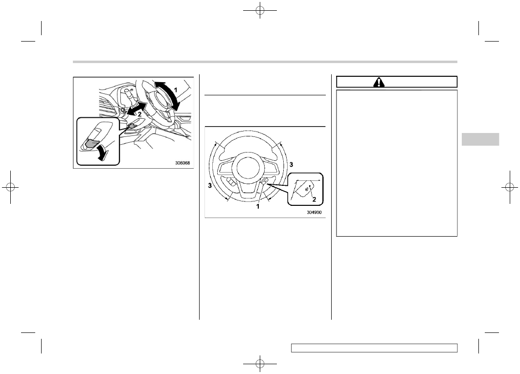
(281,1)
1)
Tilt adjustment
2)
Telescopic adjustment
1. Adjust the seat position. Refer to “Front
Seats”
2. Pull the tilt/telescopic lock lever down.
3. Move the steering wheel to the desired
level.
4. Pull the lever up to lock the steering
wheel in place.
5. Make sure that the steering wheel is
securely locked by moving it up and down,
and forward and backward.
3-19. Heated Steering Wheel
System (If Equipped)
The Heated Steering Wheel system
warms the steering wheel at a constant
temperature.
1)
Heated Steering Wheel switch
2)
Indicator light
3)
Heated area
To turn on the Heated Steering Wheel
system, pull the Heated Steering Wheel
switch when the ignition switch is in the
“ACC” or “ON” position. Then the steering
wheel will be warmed and the indicator
light on the switch will illuminate. To turn off
the Heated Steering Wheel system, pull
the switch again. Then the indicator light
will turn off.
CAUTION
.
Use the Heated Steering Wheel
system with the engine running.
Otherwise, the battery voltage
may drop below the permissible
level and it may not be possible to
start the engine.
.
There is a possibility that people
with delicate skin may suffer
slight burns even at low tempera-
tures if they use the Heated
Steering Wheel for a long period
of time. When using the Heated
Steering Wheel, always be sure to
warn the persons concerned.
.
Do not cover the Heated Steering
Wheel with an object such as a
steering wheel cover. Doing so
may cause the Heated Steering
Wheel to overheat.
NOTE
.
If the surface temperature of the
steering wheel is approximately above
104
8
F (40
8
C) when the Heated Steering
Wheel system is turned on, the system
will not heat the steering wheel. Then,
the indicator light will continue to
illuminate.
– CONTINUED –
Heated Steering Wheel System
279
3
Instruments
and
Controls
(282,1)
.
The Heated Steering Wheel system
will automatically turn off approxi-
mately 30 minutes after the system
has been turned on.
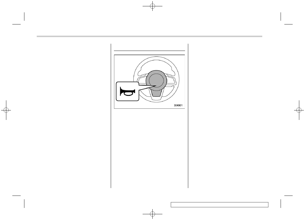
3-20. Horn
To sound the horn, push the horn pad.
Horn
280
(283,1)
4-1. Ventilator Control. . . . . . . . . . . 282
Center Ventilators . . . . . . . . . . . ... 282
Side Ventilators . . . . . . . . . . . . .. 282
Rear Ventilators (If Equipped) . . . . . . . . 282
4-2. Climate Control Panel . . . . . . . . . 283
Dual 7.0-Inch Display Models . . . . . . . .. 284
11.6-Inch Display Models . . . . . . . . . 287
4-3. Automatic Climate Control Operation. . ... 290
Sensors. . . . . . . . . . . . . . . .. 291
4-4. Manual Climate Control. . . . . . . . .. 292
Airflow Mode Selection . . . . . . . . . ... 292
Temperature Control . . . . . . . . . . ... 293
Fan Speed Control. . . . . . . . . . . .. 293
Air Conditioner Control. . . . . . . . . ... 294
Air Inlet Selection . . . . . . . . . . . ... 294
To Turn Off the Climate Control System . . . .. 294
4-5. Front Seat Heater and Ventilation
(If Equipped) . . . . . . . . . . . . .. 295
Front Seat Heater . . . . . . . . . . . ... 295
Front Seat Ventilation . . . . . . . . . . . 295
4-6. Defrosting . . . . . . . . . . . . . . 296
4-7. Operating Tips for Heater and Air
Conditioner . . . . . . . . . . . . . 297
Cleaning Ventilator Grille. . . . . . . . . 297
Efficient Cooling after Parking in Direct
Sunlight . . . . . . . . . . . . . . ... 297
Lubrication Oil Circulation in the Refrigerant
Circuit. . . . . . . . . . . . . . . .. 297
Checking Air Conditioning System before
Summer Season. . . . . . . . . . . ... 297
Cooling and Dehumidifying in High Humidity
and Low Temperature Weather Condition . . . 297
Air Conditioner Compressor Shut-Off When
Engine Is Heavily Loaded . . . . . . . . . 297
Refrigerant for Your Climate Control System . .. 298
4-8. Air Filtration System . . . . . . . . . ...298
Replacing the Cabin Air Filter. . . . . . . . 298
Climate Control
4
Climate
Control
(284,1)
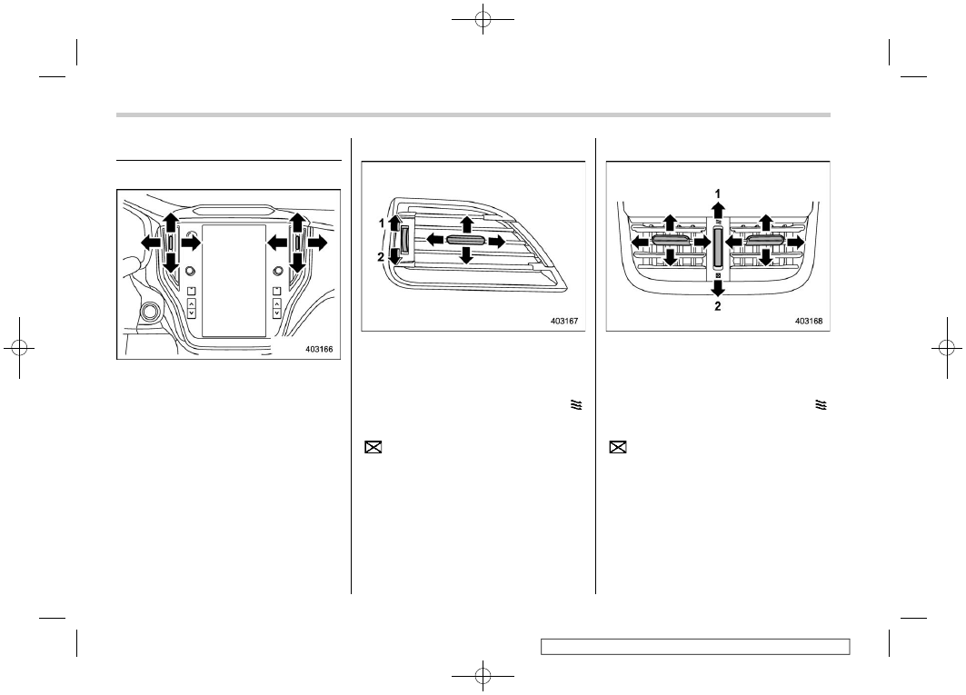
4-1. Ventilator Control
&
Center Ventilators
Move the tabs to adjust the flow direction.
To close the ventilator, move the tab all the
way down.
&
Side Ventilators
1)
Open
2)
Close
Move the tab to adjust the flow direction.
To open the ventilator, turn the side grille
open/close wheel upward to the “ ”
position.
To close it, turn the wheel downward to the
“
” position.
&
Rear Ventilators (If Equipped)
1)
Open
2)
Close
Move the tab to adjust the flow direction.
To open the ventilator, turn the rear grille
open/close wheel upward to the “ ”
position.
To close it, turn the wheel downward to the
“
” position.
Ventilator Control
282
(285,1)
4-2. Climate Control Panel
WARNING
.
The cooling function operates
only when the engine is running.
.
Do not leave children or adults
who would normally require the
support of others alone in your
vehicle. Pets should not be left
alone either. On hot, sunny days,
temperatures in a closed vehicle
could quickly become high en-
ough to cause severe or possibly
fatal injuries to people or ani-
mals.
– CONTINUED –
Climate Control Panel
283
4
Climate
Control
(286,1)
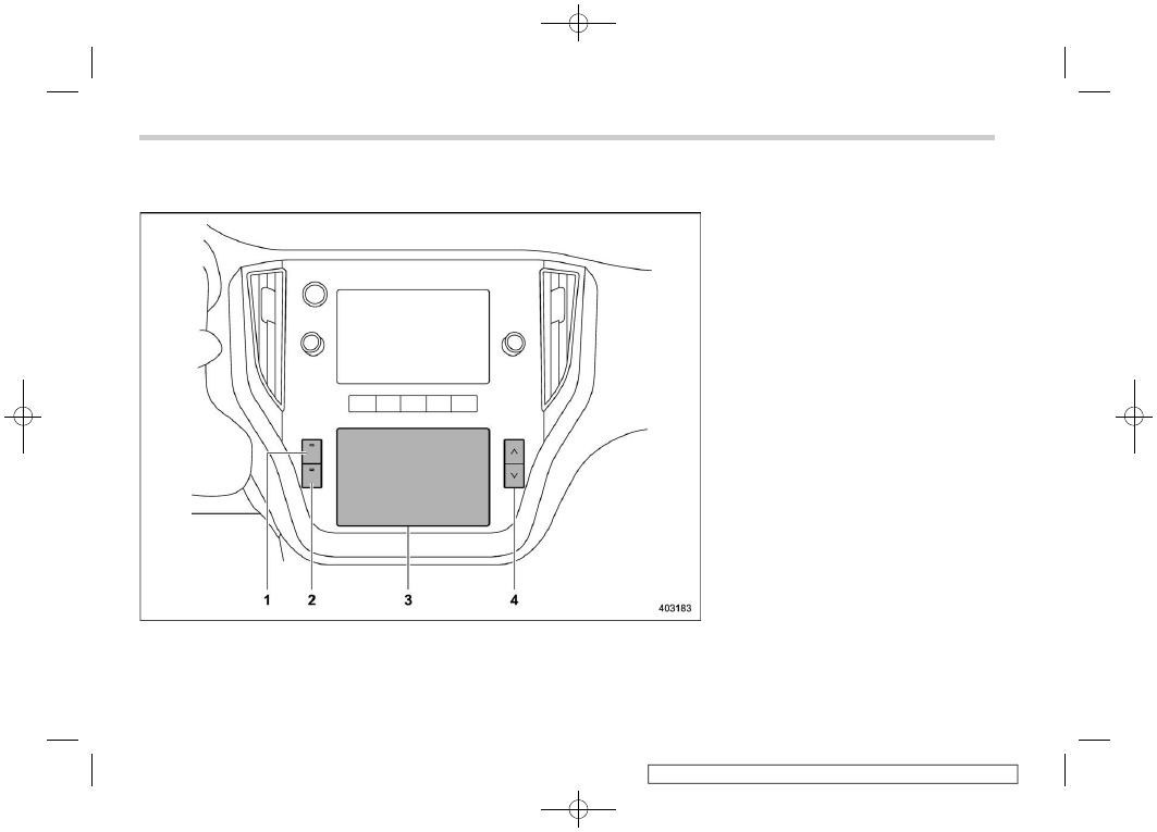
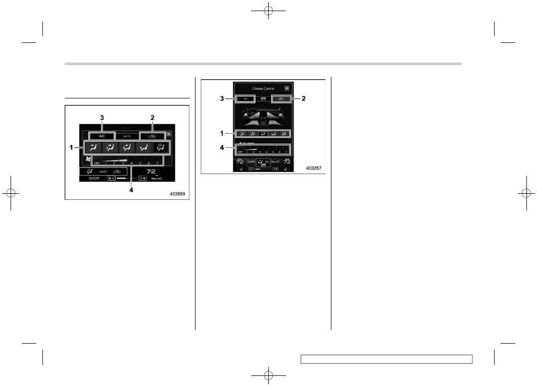
&
Dual 7.0-Inch Display Models
1)
Defroster button (Refer to “Defrosting”
2)
Rear window and outside mirror defogger
button (if equipped) (Refer to “Defogger
and Deicer”
3)
Climate control screen (lower display)
4)
Temperature control button (Refer to
“Temperature Control”
Climate Control Panel
284
(287,1)
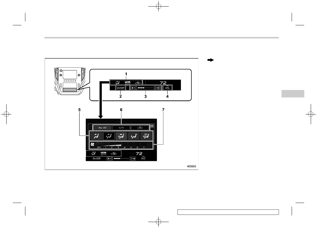
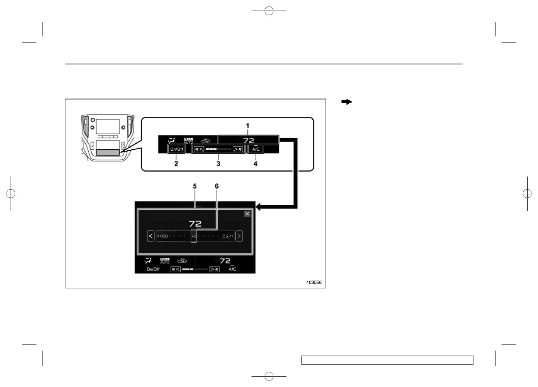
!
Climate control screen
Climate control screen (lower display)
: Touch the climate control mode indicator
1)
Climate control mode indicator
2)
Climate control ON/OFF button
3)
Fan speed indicator
4)
Customizable icon*
5)
Airflow mode selection screen
6)
Climate control mode select button
7)
Fan speed control screen
*: The customizable icon can be changed to
the favorite icon. Refer to “General settings”
– CONTINUED –
Climate Control Panel
285
4
Climate
Control
(288,1)
!
Temperature control screen
Climate control screen (lower display)
: Touch the set temperature indicator
1)
Set temperature indicator
2)
Climate control ON/OFF button
3)
Fan speed indicator
4)
Customizable icon*
5)
Temperature control screen
6)
Temperature control bar
*: The customizable icon can be changed to
the favorite icon. Refer to “General settings”
Climate Control Panel
286
(289,1)
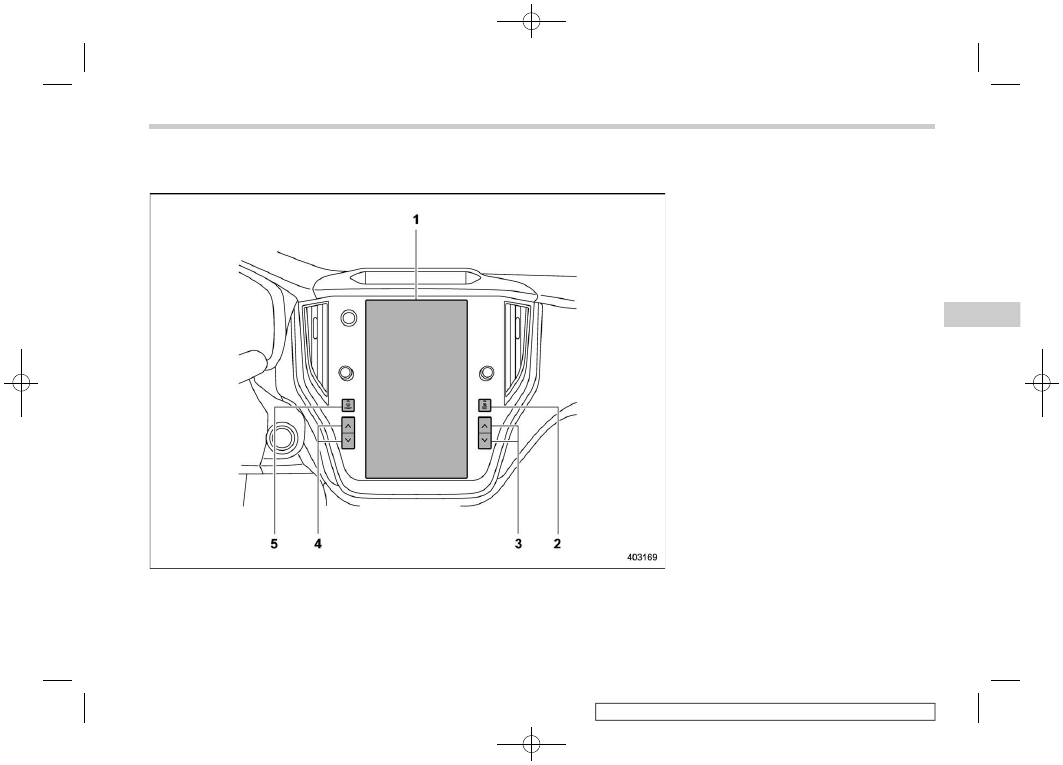
&
11.6-Inch Display Models
1)
Climate control screen
2)
Rear window and outside mirror defogger
button (Refer to “Defogger and Deicer”
3)
Passenger’s side temperature control
button (Refer to “Temperature Control”
4)
Driver’s side temperature control button
(Refer to “Temperature Control”
5)
Defroster button (Refer to “Defrosting”
– CONTINUED –
Climate Control Panel
287
4
Climate
Control
(290,1)
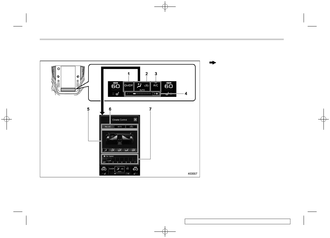
!
Climate control screen
: Touch the climate control mode indicator
1)
Climate control ON/OFF button
2)
Climate control mode indicator
3)
Customizable icon*
1
4)
Fan speed indicator
5)
Airflow mode selection screen
6)
Climate control mode select button
7)
Fan speed control screen
*1: The customizable icon can be changed to
the favorite icon. Refer to “General set-
tings”
Climate Control Panel
288
(291,1)
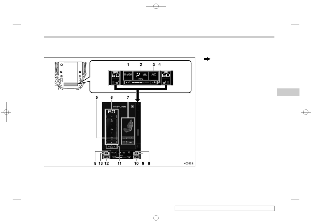
!
Temperature control screen
: Touch the temperature control screen
1)
Climate control ON/OFF button
2)
Climate control mode indicator
3)
Customizable icon*
1
4)
Fan speed indicator
5)
Temperature control bar
6)
Temperature control screen
7)
Seat heater/ventilation control screen*
2
8)
SYNC mode indicator
9)
Set temperature indicator (Passenger’s
side)
10) Front passenger’s seat heater/ventilation
indicator (if equipped)*
2
11) SYNC button
12) Driver’s seat heater/ventilation indicator
(if equipped)*
2
13) Set temperature indicator (Driver’s side)
*1: The customizable icon can be changed to
the favorite icon. Refer to “General set-
tings”
*2: For details, refer to “Front Seat Heater and
Climate Control Panel
289
4
Climate
Control
(292,1)
4-3. Automatic Climate Con-
trol Operation
Climate control screen (dual 7.0-inch dis-
play models)
Climate control screen (11.6-inch display
models)
1)
Airflow distribution
2)
Air inlet selection
3)
Air conditioner compressor
4)
Fan speed
When the full auto mode is selected, the
following functions are automatically con-
trolled.
.
Fan speed
.
Airflow distribution
.
Air inlet selection
.
Air conditioner compressor operation
To activate this mode, perform the follow-
ing.
1. Touch the climate control mode indi-
cator.
2. Touch “AUTO”.
3. Set the preferred temperature. Refer to
“Temperature Control”
NOTE
.
Operate the automatic climate con-
trol system when the engine is running.
.
Even when cooling is not necessary,
the air conditioner compressor will
automatically turn on if the temperature
is set much lower than the current
outlet air temperature. Even in this
case, the “A/C” indicator light on the
climate control screen illuminates.
.
The air conditioner may not operate
in the following cases:
– When the cabin temperature is
low
– When the ambient temperature
decreases close to 32
8
F (0
8
C)
.
The controllable temperature range
may vary depending on the regional
specifications of the vehicle.
.
If something other than temperature
control is operated while the display is
in full auto mode, the “FULL” indicator
will turn off and the “AUTO” indicator
light will remain illuminated. You can
then manually control the system as
desired using the climate control
screen. To change the system back to
full auto mode, touch “AUTO”.
Automatic Climate Control Operation
290
(293,1)
To turn off the climate control system,
touch “ON/OFF”.
At this time, the air inlet selection mode will
differ depending on the auto mode and
manual mode.
Auto mode: Changes to the outside air
circulation mode.
Manual mode: Continues the mode when
the climate control mode is set to OFF.
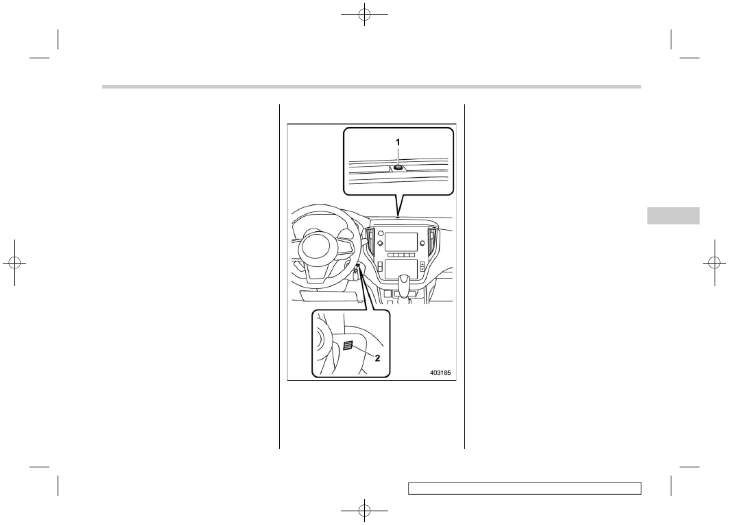
&
Sensors
1)
Solar sensor
2)
Interior air temperature sensor
The automatic climate control system
employs several sensors. These sensors
are delicate. If they are treated incorrectly
and become damaged, the system may
not be able to control the interior tempera-
ture correctly. To avoid damaging the
sensors, observe the following precau-
tions:
– Do not subject the sensors to impact.
– Keep water away from the sensors.
– Do not cover the sensors.
Automatic Climate Control Operation
291
4
Climate
Control
(294,1)
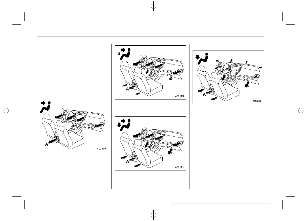
4-4. Manual Climate Control
&
Airflow Mode Selection
Select the preferred airflow mode by the
following operation.
Via the climate control screen:
1. Touch the climate control mode indi-
cator.
2. Touch the preferred airflow mode.
Airflow modes are as follows.
A)
Models with rear ventilators
Ventilation: Instrument panel outlets
A)
Models with rear ventilators
Ventilation 2: Instrument panel outlets and
foot outlets
A)
Models with rear ventilators
Bi-level: Instrument panel outlets and the
foot outlets
A)
Models with rear ventilators
Heat: Foot outlets, both side outlets of the
instrument panel and some through wind-
shield defroster outlets (A small amount of
air flows to the windshield and both side
windows to prevent fogging.)
Manual Climate Control
292
Нет комментариевНе стесняйтесь поделиться с нами вашим ценным мнением.
Текст