Volvo 850. Manual — part 63
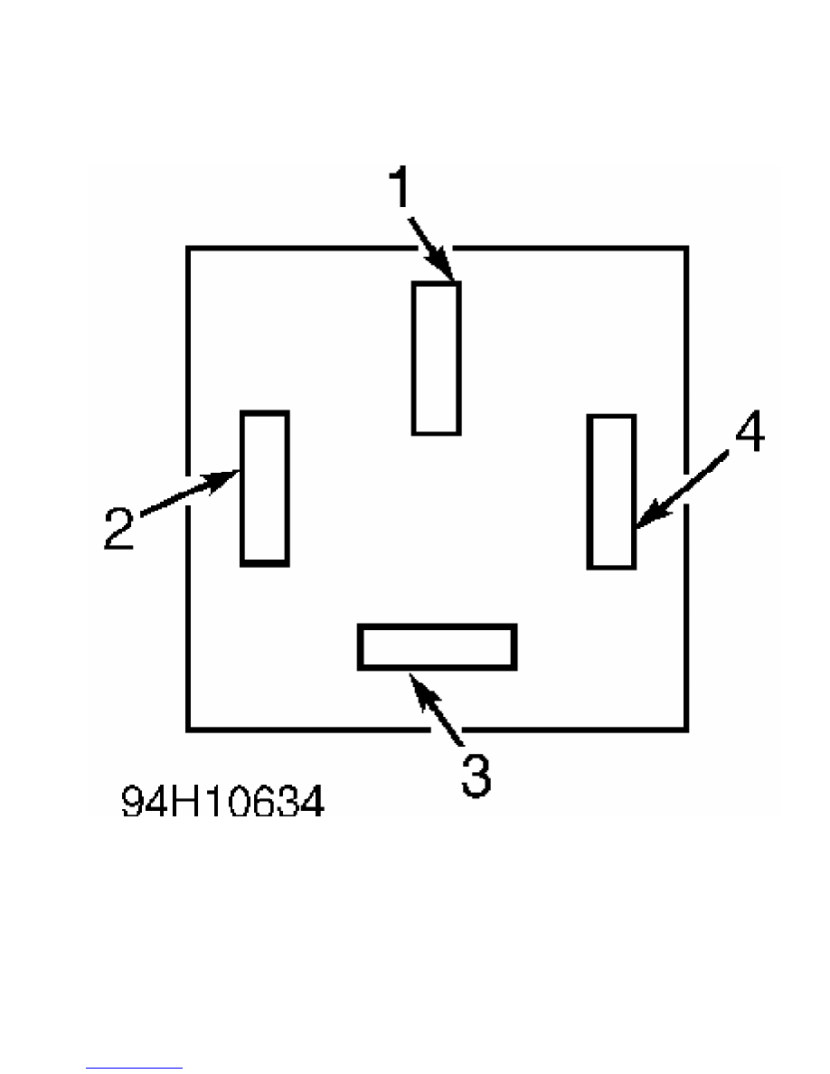
Fig. 12: Identifying A/C Relay Connector Terminals
Courtesy of Volvo Cars of North America.
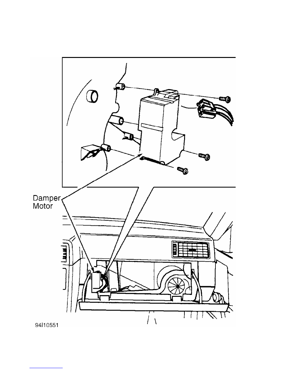
Fig. 13: Removing Damper Motor
Courtesy of Volvo Cars of North America.
DTC 2-1-2, 2-2-2, 2-3-2, 2-3-4 & 2-3-6 DRIVER’S OR
PASSENGER’S SIDE DAMPER MOTOR POSITION SENSOR
SHORTED TO GROUND
1) Check if DTCs 2-1-2, 2-2-2, 2-3-2, 2-3-4, and 2-3-6 are
all present together. If all DTCs are not present, there is a short
circuit in ground wire between ECC control unit and damper motor which
applies to DTC. See AUTOMATIC A/C-HEATER SYSTEM DIAGNOSTIC TROUBLE
CODES table, then go to next step. If all DTCs are present, an open
circuit is present in common voltage circuit at ECC terminal A8. See
Fig. 10.
2) Ensure ignition is off. Connect test unit between ECC
control module and control unit connector. Check ECC grounds. See DTC
1-2-1, OUTSIDE TEMP. SENSOR CIRCUIT SHORTED TO GROUND. Also check
power supply to damper motor position sensor. See TEST MODE 2 under
TROUBLE SHOOTING. If ECC grounds and power supply to damper motor
position sensor are okay, go to next step.
3) Turn ignition off. Disconnect ECC control module, but
leave test unit connected to ECC control module connector. Disconnect
6-pin damper motor connector. See Figs. 11-13. Connect ohmmeter
between test unit pin No. 10 and pin indicated in DAMPER MOTOR TEST
UNIT PIN NUMBERS (RESISTANCE CHECK) table.
DAMPER MOTOR TEST UNIT PIN NUMBERS (RESISTANCE CHECK)
Pin No. Damper Motor
10 & 17 . . . . . . . . . Driver’s Side
10 & 18 . . . . . . . . . Passenger’s Side
10 & 20 . . . . . . . . . .. Ventilation
10 & 19 . . . . . . . . . Floor/Defrost
10 & 21 . . . . . . . . . Recirculation
4) If ohmmeter indicates continuity, short circuit is present
in wiring at terminal No. 3. If ohmmeter indicates no continuity,
wiring is okay. Go to next step.
5) Ensure ignition is off. Disconnect damper motor connector.
Connect ohmmeter between damper motor terminals No. 1 and 3. See
Fig. 11. Turn damper motor output shaft. Ohmmeter reading should vary
between 0-12,000 ohms.
6) If resistance is to specification, check voltage supply
circuit between motor connector terminal No. 2 and ECC control module
terminal A8. If resistance is a constant zero ohms, a short is present
in damper motor position sensor. Replace damper motor.
DTC 3-1-1, 3-1-2, 3-1-3, 3-1-4 & 3-1-5 DAMPER MOTOR SHORTED
TO GROUND OR POWER
1) Turn ignition off. Connect test unit between ECC control
module and ECC control module connector. Check system ground circuits.
See DTC 1-2-1, OUTSIDE TEMP SENSOR CIRCUIT SHORTED TO GROUND. If
ground circuits are okay, go to next step.
2) Turn ignition on. Connect one voltmeter lead to test unit
pin No. 10 and other lead to test unit pin No. 31 (driver’s damper
motor), No. 33 (passenger’s side damper motor), No. 37 (ventilation
damper motor), No. 35 (floor/defrost damper motor), or No. 39
(recirculation damper motor). Voltmeter should vary from 0-4 volts.
3) If voltmeter indicates zero volts, wire is shorted to
ground. If voltmeter indicates battery voltage, wire is shorted to
voltage. Turn ignition off. Disconnect suspect damper motor connector.
Check wiring between motor connector and ECC control module.
DTC 3-2-1, 3-2-2, 3-2-3, 3-2-4 & 3-2-5
DAMPER MOTOR ACTIVE TOO LONG
1) Check if DTCs 3-2-1, 3-2-2, 3-2-3, 3-2-4, and 3-2-5 are
also present. If all DTCs are present, vehicle may be equipped with an
ECC control module for a right-hand-drive vehicle, or vice versa.
Check ECC terminal A28. See Fig. 10. ECC control module for left-hand-
drive vehicles should not have terminal A28 grounded.
2) If terminal is okay, perform self-adjustment of damper
motor limit positions under TEST MODE 4. If motor limit positions are
adjusted correctly, check ECC system ground circuits. See DTC 1-2-1,
OUTSIDE TEMP. SENSOR CIRCUIT SHORTED TO GROUND. If ground circuits
check okay, go to next step.
3) Ensure test unit is connected to ECC control module. Turn
ignition on. Connect one voltmeter lead to test unit pin No. 10 and
other lead to test unit pin No. 31 (driver’s side damper motor), No.
33 (passenger’s side damper motor), No. 37 (ventilation damper motor),
No. 35 (floor/defrost damper motor), or No. 39 (recirculation damper
motor).
4) Rotate air circulation knob to and from different settings
while observing voltmeter. Voltmeter should show control voltage of
about 0-12 volts while damper is moving to its new setting. If
voltmeter shows about 0-12 volts for longer than about 12 seconds,
check if damper is stuck in position. Replace damper if not stuck.
DTC 4-1-1 PASSENGER COMPARTMENT FAN OVERCURRENT OR SEIZED FAN
1) Turn ignition off. Disconnect passenger compartment
(blower) fan electrical connector. Check if fan turns freely by hand.
If fan does not turn freely, replace fan. Check fan location for
anything that could cause blockage and clear as necessary.
2) If fan is okay, erase DTC. If DTC returns, there may be a
fault in power stage surge protector. See DTC 4-1-9, ECC POWER STAGE
EMITTING FAULTY DIAGNOSTIC SIGNAL.
DTC 4-1-2 & 4-1-5 DRIVER’S OR PASSENGER’S SIDE TEMP.
SENSOR INTAKE FAN SHORTED TO GROUND
1) Ensure ignition is off. Connect test unit to ECC control
module. Check ground circuits. See DTC 1-2-1, OUTSIDE TEMP. SENSOR
CIRCUIT SHORTED TO GROUND. If ground circuits are okay, turn ignition
off. Disconnect test unit from ECC control module, but leave it
connected to ECC control module connector. Disconnect passenger
compartment temperature sensor connector.
2) Check driver’s side fan by connecting an ohmmeter between
test unit pins No. 6 and 45. Check passenger’s side fan by connecting
an ohmmeter between test unit pins No. 6 and 46. If ohmmeter indicates
continuity, wiring is shorted to ground or voltage. If ohmmeter
indicates no continuity, wiring is okay.
3) Ensure ignition is off. Disconnect passenger compartment
temperature sensor connector. Connect an ohmmeter between passenger
compartment temperature sensor connector terminals No. 2 and 4. See
Fig. 6. Ohmmeter should indicate about 50,000 ohms. If ohmmeter
indicates continuity, intake fan is shorted. Replace fan and
temperature sensor.
DTC 4-1-3 & 4-1-6 DRIVER’S OR PASSENGER’S SIDE TEMP.
SENSOR INTAKE FAN, NO CONTROL VOLTAGE
1) Ensure ignition is off. Connect test unit to ECC control
module. Check ground circuits. See DTC 1-2-1, OUTSIDE TEMP. SENSOR
CIRCUIT SHORTED TO GROUND. If ground circuits are okay, go to next
step.
2) Ensure ignition is off. Disconnect test unit from ECC
control module, but leave it connected to ECC control module
Нет комментариевНе стесняйтесь поделиться с нами вашим ценным мнением.
Текст